Automatic lifting locking mechanism

A locking mechanism and automatic lifting technology, applied in the field of radar, can solve the problems that the radar lifting mechanism cannot provide

Active Publication Date: 2020-07-28
CHINA ELECTRONIC TECH GRP CORP NO 38 RES INST
View PDF7 Cites 3 Cited by
  • Summary
  • Abstract
  • Description
  • Claims
  • Application Information

AI Technical Summary

Problems solved by technology

[0003] The technical problem to be solved by the present invention is: the radar lifting mechanism in the prior art cannot provide a stable working platform, which leads to the technical problem that the radar cannot perform high-precision measurement

Method used


Image

  • Automatic lifting locking mechanism
  • Automatic lifting locking mechanism
  • Automatic lifting locking mechanism

Examples


Embodiment 1

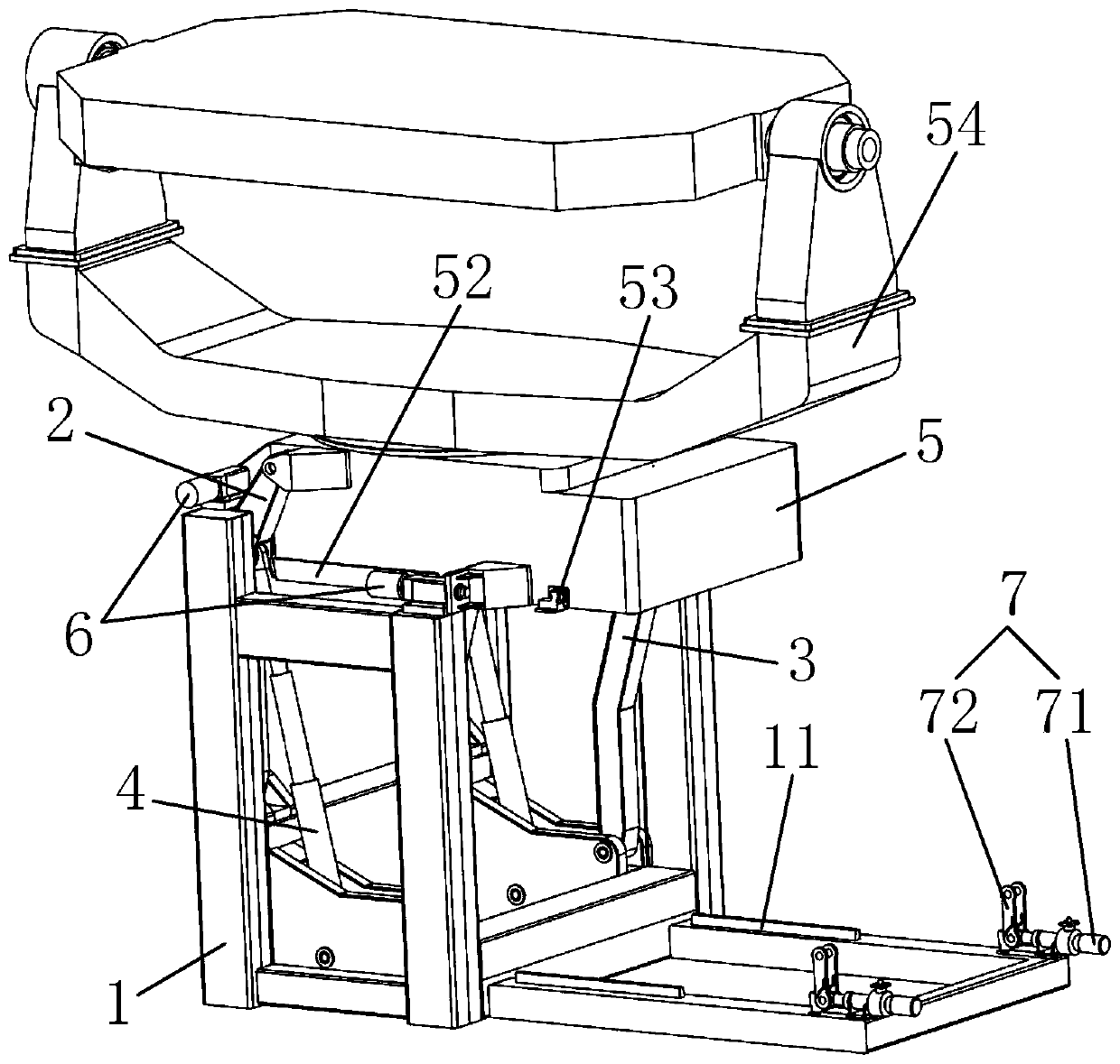
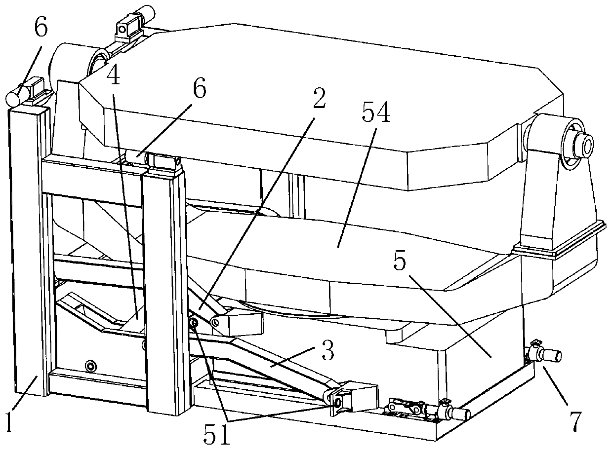
[0045] Such as figure 1 As shown, an automatic lifting locking mechanism includes a bracket 1 , a first connecting rod 2 , a second connecting rod 3 , a lifting drive mechanism 4 , a lifting platform 5 , and an upper locking mechanism 6 .

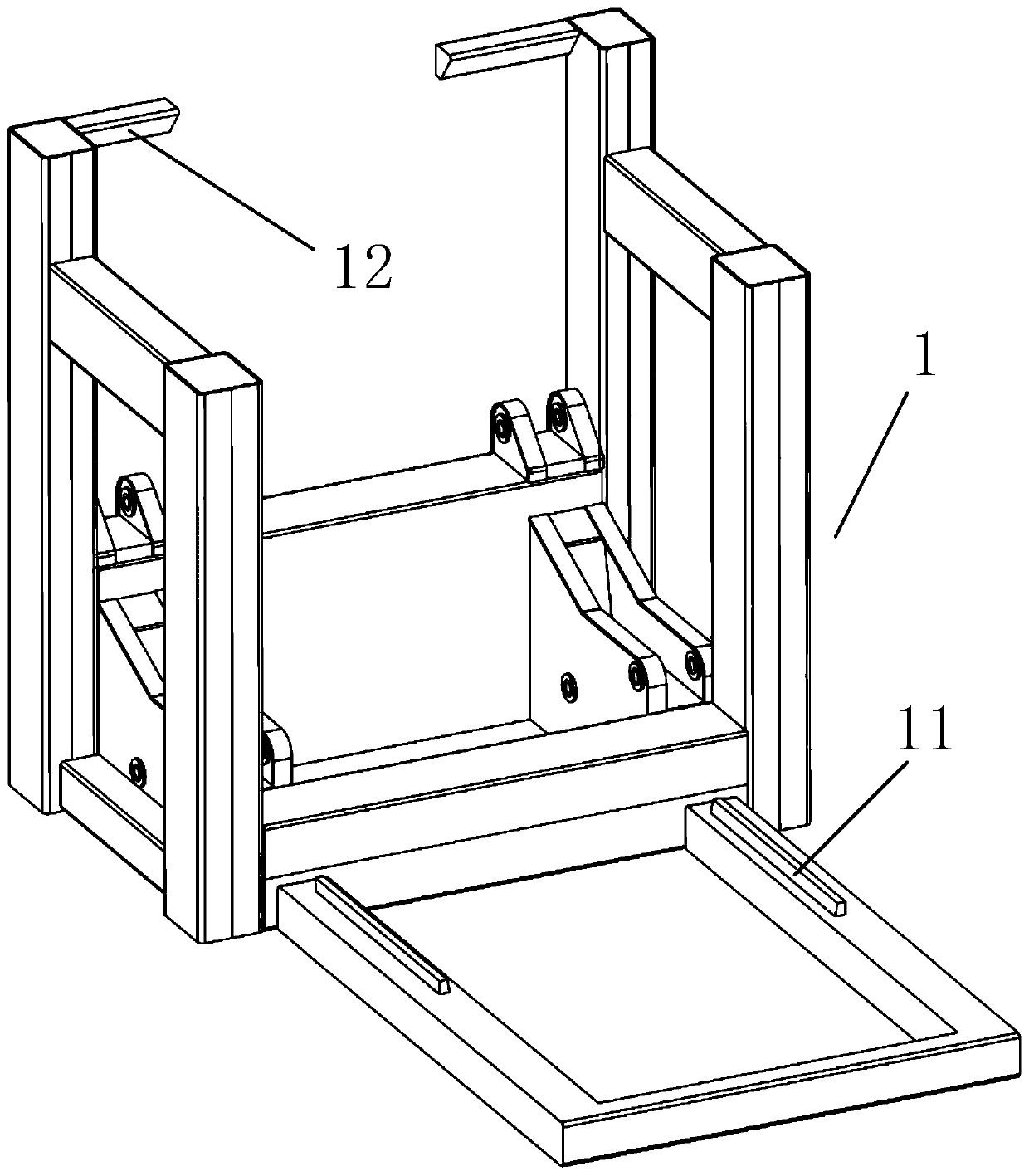
[0046] Such as image 3 As shown, in this embodiment, the main function of the bracket 1 is to provide installation positions for the rest of the components. The bracket 1 is not limited to a specific shape, as long as it can meet the requirements of installing and matching each component, and realize the corresponding functions. Yes, for the convenience of subsequent description, specify figure 1 The position indicated by the mark "1" is the front, and other orientations are based on this.

[0047] Such as figure 1 , 2As shown, the upper part of the first connecting rod 2 and the second connecting rod 3 are bent to the right relative to the lower part. The connection line between the hinge points on the connecting rod 2 is parallel to...

Embodiment 2

[0057] The difference between this embodiment and Embodiment 1 is:

[0058] Such as figure 1 , 3 As shown, the support 1 is provided with a first positioning wedge surface 11, the first positioning wedge surface 11 is arranged on the front and rear sides of the support 1 at the drop position of the lifting platform 5, and the front and rear two first positioning wedge surfaces 11 are located between the planes. The line of intersection is located below the two, and this line of intersection is along the left-right direction. The second positioning wedge surface 52 that cooperates with the first positioning wedge surface 11 is set on the lifting platform 5, and the second positioning wedge surface 52 and the first positioning wedge surface 52 are dropped by the lifting platform 5 to match the first positioning wedge surface. The wedge surface 11 cooperates to realize positioning.

[0059] Such as figure 1 , 2 , 6, it also includes a lower locking mechanism 7 arranged on the...

Embodiment 3

[0061] The difference between this embodiment and Embodiment 1 is:

[0062] Such as image 3 As shown, the bracket 1 is provided with a stopper 12. After the lifting platform 5 is raised, the stopper 12 can block the first connecting rod 2 or the second connecting rod 3 or the lifting platform 5 at the upper limit position. Among them, a stopper 12 is respectively arranged on the front and rear sides of the upper left part of the bracket 1. After the lifting platform 5 rises, the stopper 12 can block the first connecting rod 2 at the upper limit position, and the positioning pin driving mechanism 61 is installed on the stopper 12. superior.


PUM


Abstract

The invention discloses an automatic lifting locking mechanism. The automatic lifting locking mechanism comprises a support, a first connecting rod, a second connecting rod, a lifting driving mechanism, a lifting table and upper locking mechanisms; the two ends of the first connecting rod and the two ends of the second connecting rod are hinged to the support and the lifting table, and the projections of all hinge shafts in the vertical plane perpendicular to the hinge shafts are located at the four corners of a virtual parallelogram; the lifting driving mechanism is arranged on the support, and the movable end is connected to the first connecting rod or the second connecting rod or the lifting platform; and the upper locking mechanisms comprise positioning pin driving mechanisms arrangedon the support, positioning pins are arranged at the movable ends of the positioning pin driving mechanisms, at least two sets of upper locking mechanisms are arranged, at least one positioning pin isperpendicular to the remaining positioning pins, positioning holes matched with the positioning pins are formed in the lifting table, and after the lifting table is lifted, the positioning pins are inserted into the corresponding positioning holes. The automatic lifting locking mechanism has the advantages that a radar lifting mechanism can provide a stable working platform, and it is ensured that a radar can conduct high-precision measurement.

Description

technical field [0001] The invention relates to the technical field of radar, in particular to an automatic lifting and locking mechanism. Background technique [0002] With the development and application of radar technology, higher and higher requirements are put forward for the mobility of radar. Among them, vehicle-mounted and ship-borne radars are more and more widely used because of their high maneuverability. These radars need to meet the requirements of various transportation conditions, and have the characteristics of integration and high degree of automation in structure. There are mainly two structural forms of turntables and antenna lifting mechanisms at home and abroad: vertical lifting type and folding type. The vertical lifting type takes up little space in the length direction of the car body, has poor stability and rigidity, and requires special processing technology. It is difficult to design and process, and it is difficult to apply to occasions where the...

Claims


Application Information

Patent Timeline
Patent Type & Authority Applications(China)
IPC IPC(8): F16M11/26F16M11/16B60Q9/00B63B49/00
CPCF16M11/26F16M11/16B60Q9/00B63B49/00
Inventor 张腊梅李旺何张强张根烜关宏山钱海涛钱江蓉王晓红王振收徐非骏李俊英吴后平
Owner CHINA ELECTRONIC TECH GRP CORP NO 38 RES INST
Why Eureka
Try Eureka