Ground subsidence monitoring device for subway tunnel construction
A technology for tunnel construction and land subsidence, applied in measurement devices, surveying and navigation, height/level measurement, etc., can solve the problems of inconvenient observation and insufficient settlement monitoring methods, and achieve the effect of improving practicability
- Summary
- Abstract
- Description
- Claims
- Application Information
AI Technical Summary
Problems solved by technology
Method used
Image
Examples
Embodiment 1
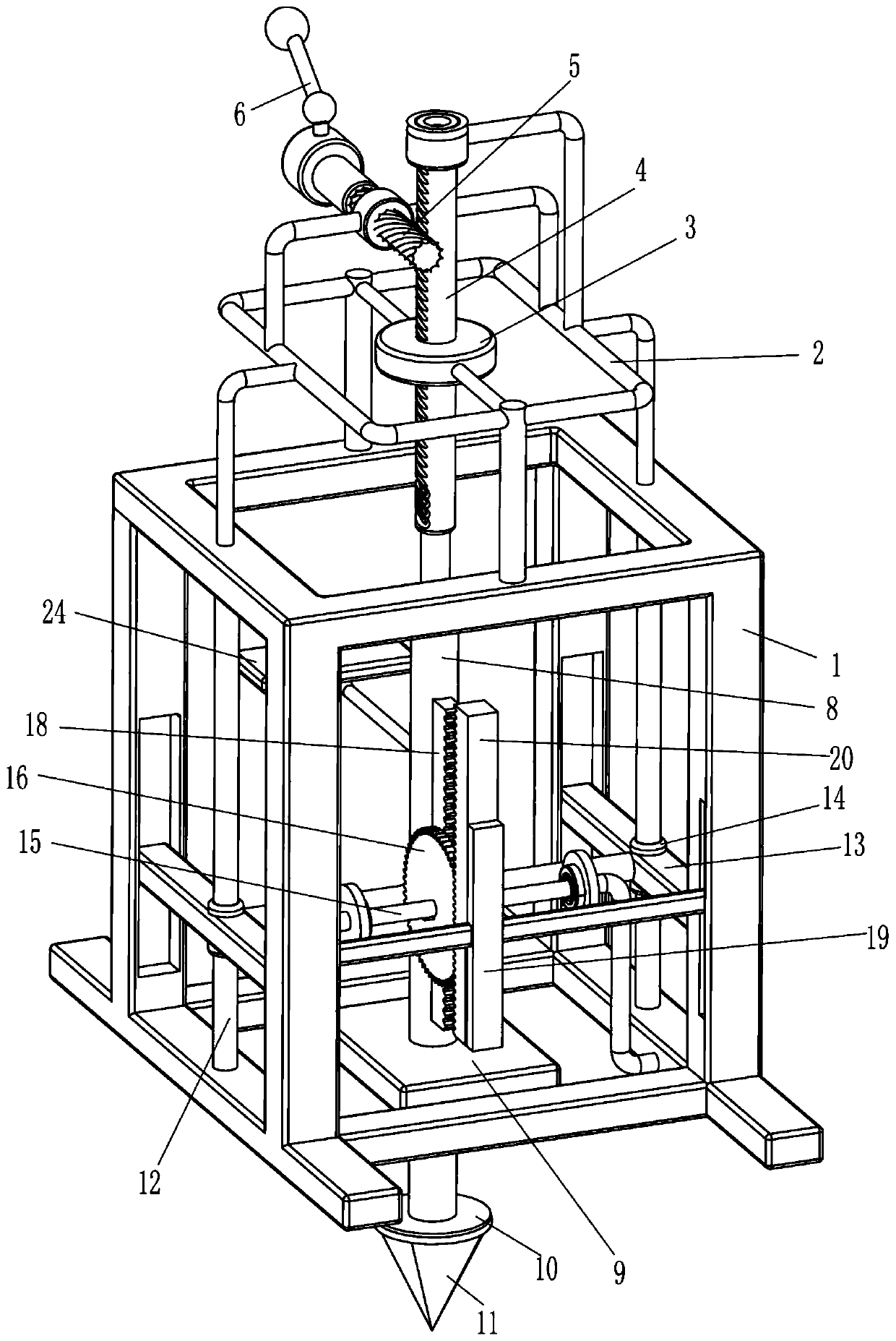
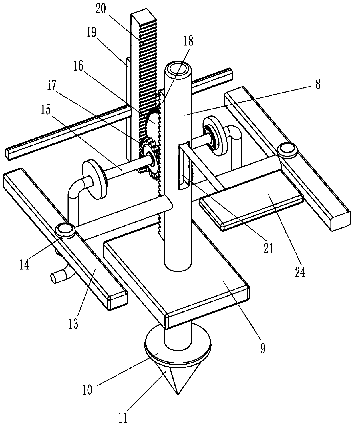
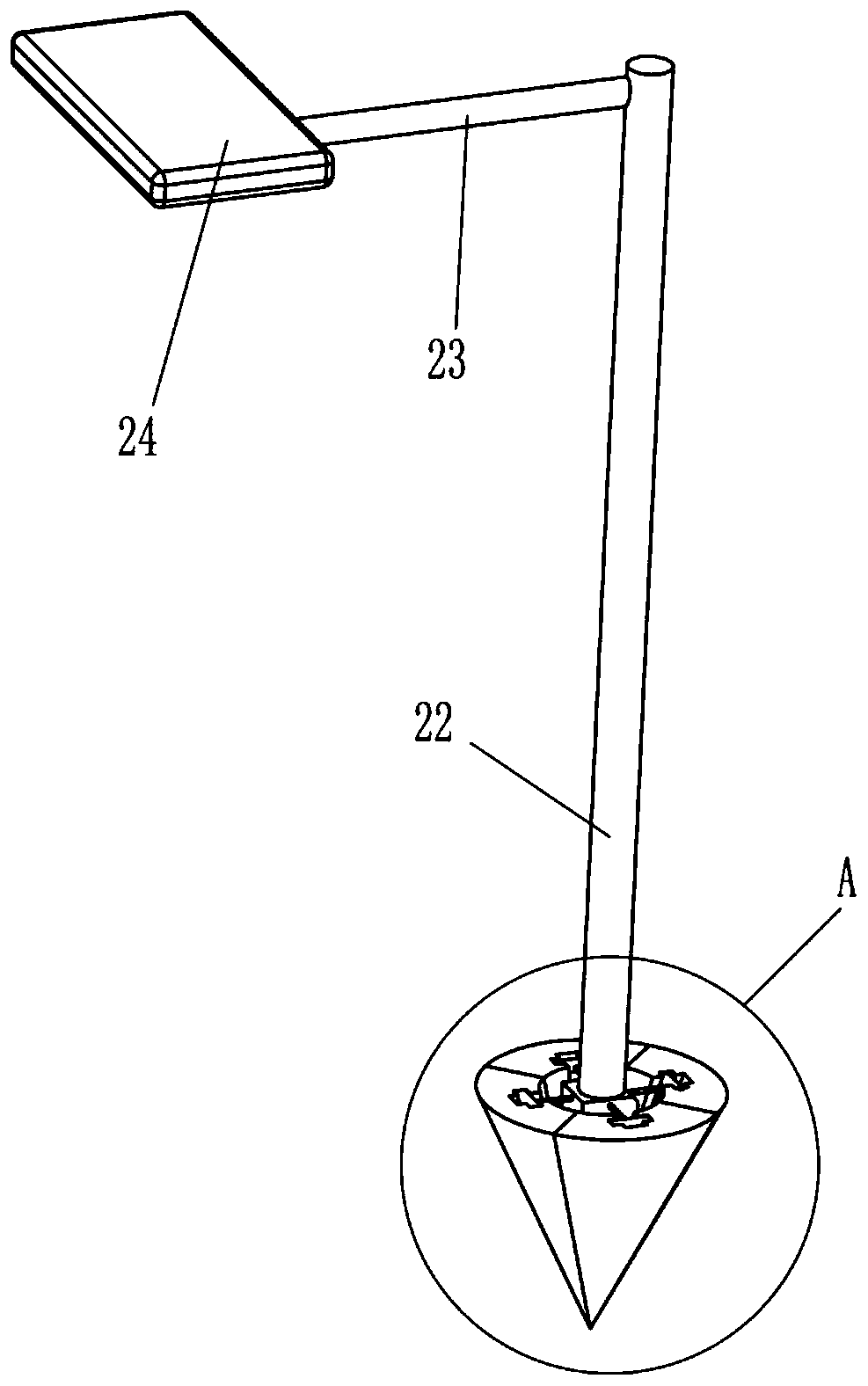
[0020] A ground subsidence monitoring device for subway tunnel construction, such as figure 1 and 2 As shown, it includes a bracket 1, a drive-in and pull-out component and a monitoring component. The top of the bracket 1 is provided with a drive-in and pull-out component that is driven in and out by rotation, and the lower part of the drive-in and pull-out component is provided with a through A monitoring component for reaction monitoring in a lifting mode.
[0021] Such as figure 1 As shown, the drive-in and pull-out assembly includes a mounting frame 2, a first guide sleeve 3, a helical rack 4, a helical gear 5, and a crank handle 6. The top of the bracket 1 is fixed with the mounting frame 2 through bolts, and the middle part of the mounting frame 2 The first guide sleeve 3 is fixedly connected by bolts, the first guide sleeve 3 is slidingly provided with a helical rack 4, and the rear side of the top of the installation frame 2 is rotatably provided with a helical gear ...
Embodiment 2
[0027] On the basis of Example 1, such as figure 1 and 2 As shown, guide rod 12, lifting plate 13 and second guide sleeve 14 are also included, and guide rod 12 is welded in the middle of the left and right sides of support 1, and guide rod 12 is slidably provided with second guide sleeve 14. Cover 14 is provided with lifting plate 13, and lifting plate 13 is welded with first slide bar 8.
[0028] Such as figure 1 and 2 Shown, also comprise rotating bar 15, bull gear 16, pinion 17, first tooth bar 18, second connecting plate 19 and second tooth bar 20, the rotating type is provided with rotating bar between the lower part of left and right sides of support 1 15. The middle part of the rotating rod 15 is key-connected with a large gear 16 and a pinion 17. The pinion 17 is on the right side of the large gear 16. The front side of the first slide bar 8 is fixedly connected with a first rack 18 by screws. The first rack 18 Engaged with the pinion 17, the lower part of the fro...
PUM
 Abstract
Description
Claims
Application Information
 - R&D
- Intellectual Property
- Life Sciences
- Materials
- Tech Scout
- Unparalleled Data Quality
- Higher Quality Content
- 60% Fewer Hallucinations
Browse by: Latest US Patents, China's latest patents, Technical Efficacy Thesaurus, Application Domain, Technology Topic, Popular Technical Reports.
© 2025 PatSnap. All rights reserved.Legal|Privacy policy|Modern Slavery Act Transparency Statement|Sitemap|About US| Contact US: help@patsnap.com


