
Thermal shrinkage terminal

A technology of heat shrinkage and terminals, which is applied in the direction of cable joints, electrical components, electrical components, etc., can solve the problems of water vapor ingress, performance degradation and failure of joints, and achieve the effect of tight fit and reduced gap width

Pending Publication Date: 2020-07-28
上海晗普新材料科技有限公司
View PDF0 Cites 1 Cited by
  • Summary
  • Abstract
  • Description
  • Claims
  • Application Information

AI Technical Summary

Problems solved by technology

[0003] The heat-shrinkable tube and the wire cannot be completely bonded, and during use, as the heat-shrinkable tube ages, the gap between the two will gradually increase. After the gap increases, water vapor will enter, resulting in cracks at the connection. Reduced performance or even failure

Method used


Image

  • Thermal shrinkage terminal
  • Thermal shrinkage terminal
  • Thermal shrinkage terminal

Examples


Embodiment Construction

[0047] The application will be described in further detail below in conjunction with the accompanying drawings.

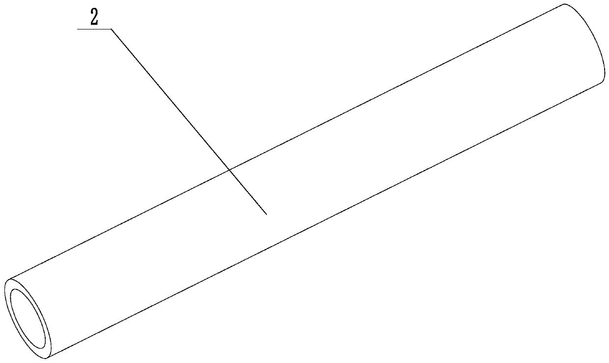
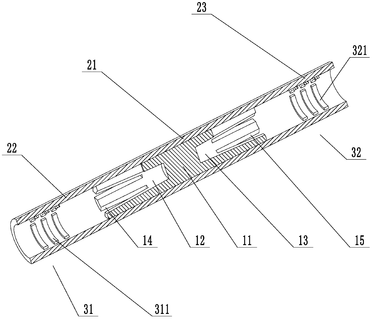
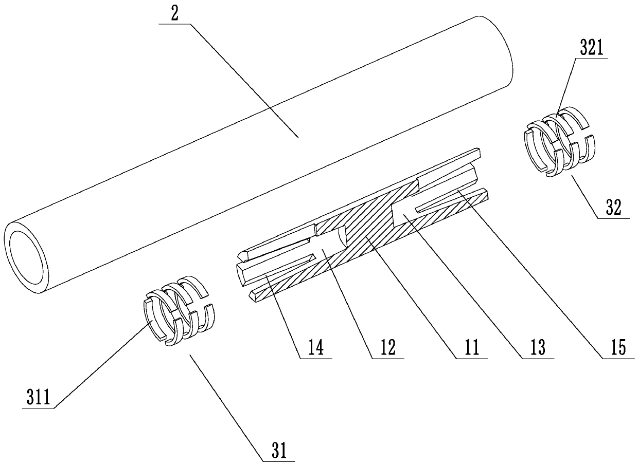
[0048] see figure 1 and figure 2 , is a heat-shrinkable terminal disclosed in the embodiment of the present application, and the heat-shrinkable terminal is mainly composed of a connecting post 11, a heat-shrinkable transparent sleeve 2, a first heat-shrinkable ring 31, a second heat-shrinkable ring 32, and the like.

[0049] The connecting column 11 is cylindrical in shape and has two circular end surfaces and a side surface. A first blind hole 12 and a second blind hole 13 are respectively provided on the two circular end surfaces. The first blind hole 12 The sum of the depth and the depth of the second blind hole 13 is less than the length of the connecting post 11 .

[0050] At least two first long grooves 14 are provided on the side wall of the connecting column 11, the bottom surface of the first long groove 14 communicates with the inner wall of the first...


PUM


Abstract

The invention relates to a thermal shrinkage terminal, which comprises a connecting column, a first blind hole, a second blind hole, at least two first long grooves, at least two second long grooves and a thermal shrinkage type transparent bushing, wherein the first blind hole and the second blind hole are formed in the two end faces of the connecting column respectively; the first long grooves are formed in the side wall of the connecting column, the second long grooves and the thermal shrinkage type transparent bushing are arranged on the side wall of the connecting column, the thermal shrinkage type transparent bushing comprises a first part sleeving the connecting column, and a second part and a third part which respectively extend outwards from two ends of the first part, a first thermal shrinkage ring is arranged on the inner wall of the second part, a second thermal shrinkage ring is arranged on the inner wall of the third part, and the surface of the first thermal shrinkage ring and the surface of the second thermal shrinkage ring are both coated with a wet water color-changing pigment. The thermal shrinkage terminal is used for connection of electrical circuits, can display water vapor infiltration, and provides a reference basis for maintenance or replacement.

Description

technical field [0001] The present application relates to the technical field of connection terminals, in particular to a heat-shrinkable terminal. Background technique [0002] Heat-shrinkable terminals are used for electrical circuit connections and have the functions of insulation, waterproof and stress protection. Most of the existing heat-shrinkable terminals have an integrated structure. After the connected wires are inserted into the inner metal tube from both sides, the heat-shrinkable tube wrapped outside the metal tube is heated with a heat gun or other heatable methods to make it close to the metal tube. on the wire. [0003] The heat-shrinkable tube and the wire cannot be completely bonded, and during use, as the heat-shrinkable tube ages, the gap between the two will gradually increase. After the gap increases, water vapor will enter, resulting in cracks at the connection. performance degradation or even failure. Contents of the invention [0004] In view o...

Claims


Application Information

Patent Timeline
IPC IPC(8): H01R4/10H01R4/72H01R11/09H02G15/18
CPCH01R4/10H01R4/726H01R11/09H02G15/18
Inventor 浦亚芹韩晓明马腾
Owner 上海晗普新材料科技有限公司
Learn More