Motorized bicycle transmission
A technology for electric bicycles and transmissions, which is applied to vehicle gearboxes, vehicle components, rider drives, etc., can solve the problems of complex design and modernization process of ordinary bicycles turning to electric bicycles
- Summary
- Abstract
- Description
- Claims
- Application Information
AI Technical Summary
Problems solved by technology
Method used
Image
Examples
Embodiment 1
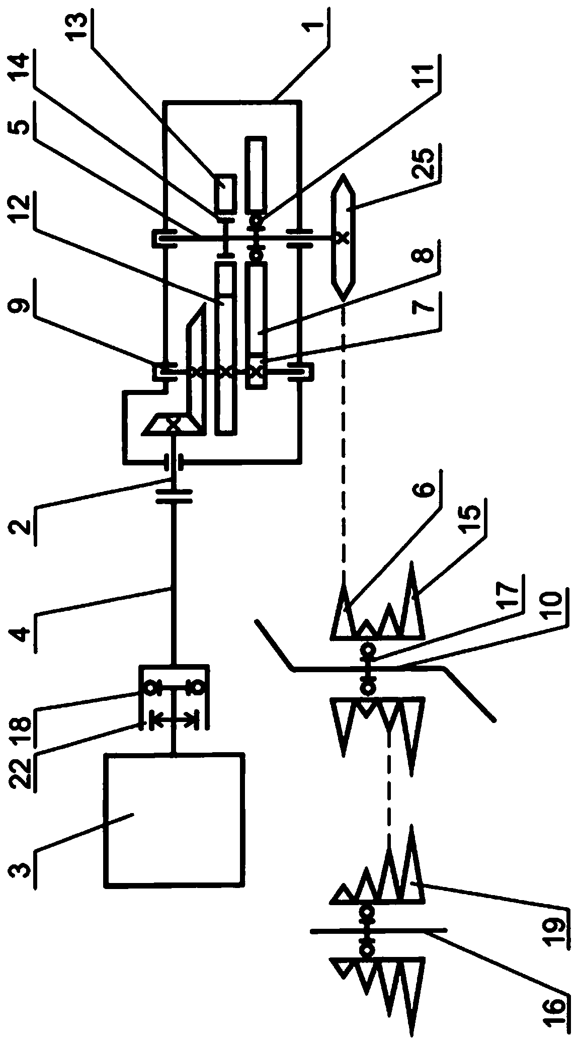
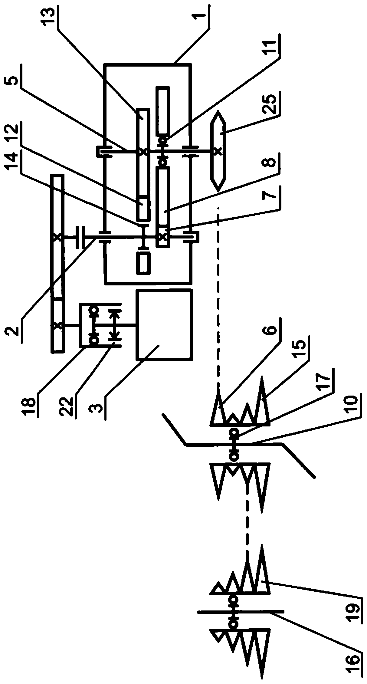
[0066] A better implementation of the electric bicycle transmission is as follows:
[0067] Inside the gearbox (1), the input shaft (2) is geared to the intermediate shaft (9).
[0068] The first and second parts of the mechanical transmission are located between the intermediate shaft (9) and the output shaft (5).
[0069] The second disc-shaped member (7) and the third disc-shaped member (8) of the first part of the mechanical transmission are compressed and mounted on the intermediate shaft (9) and the output shaft (5) respectively. The shaft-mounted element of the second disc member (7) or third disc member (8) is the first overrunning clutch (11), which only transmits the direction of rotation from the intermediate shaft (9) to the output shaft (5). to achieve figure 1 , the third disc member (8) is installed on the first overrunning clutch (11), and the second disc member (7) is fixed on the intermediate shaft (9).
[0070] The fourth disc-shaped member (12) and the f...
Embodiment 2
[0094] Example 2 is similar to Example 1. But it is different from Embodiment 1 in that the second overrunning clutch (14) and the sixth disc member (25) are connected with the output shaft (5).
[0095] The second overrunning clutch (14) is uncontrollable. On the contrary, for more comfortable use of the bicycle when the engine is idling, a sixth disc member (25) is mounted on the output shaft (5) of a lockable overrunning clutch. In the locked state, the overrunning clutch acts as a positive connection, and in the unlocked state, the overrunning clutch only transfers the direction of rotation from the output shaft (5) to the sixth disc member (25). At the same time, the corresponding control element of the lockable overrunning clutch is mounted on the bicycle handlebar as a reset lever. When the reset lever is pressed, the overrunning clutch is locked and the engine can be started by depressing the pedal. When the reset lever is released, the overrunning clutch is unlocke...
Embodiment 3
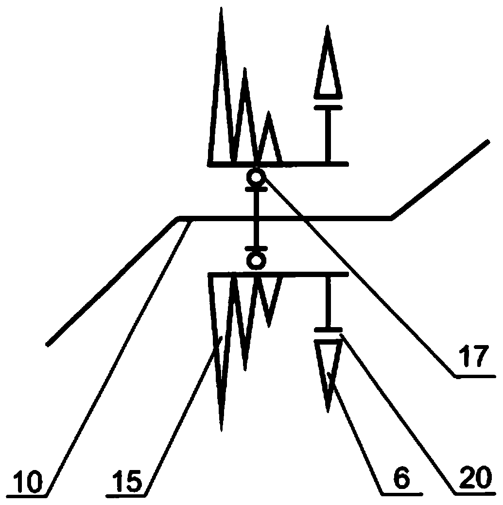
[0098] Example 3 is similar to Example 1. The difference is that the second overrunning clutch (14) and the first disc member (6) are connected with the pedal disc member (15).
[0099] The second overrunning clutch (14) is uncontrollable. On the contrary, in order to use the bicycle comfortably when the engine is idling, the first disc member (6) is fixed on the pedal disc member (15) by a lockable clutch (20) ( figure 2 ). In the locked state, the clutch (20) acts as a solid connection, and in the unlocked state acts as a one-way clutch, transmitting only the direction of rotation from the first disc member (6) to the pedal disc member (15). In this case, the corresponding control element of the clutch (20), located on the handlebar of the bicycle, is a reset lever. When the lever is pressed and held, the clutch (20) is locked and the engine can be started by pedaling. When the lever is released, the clutch (20) is unlocked.
[0100] In special cases, a clutch (20) can...
PUM
 Abstract
Description
Claims
Application Information
 - R&D Engineer
- R&D Manager
- IP Professional
- Industry Leading Data Capabilities
- Powerful AI technology
- Patent DNA Extraction
Browse by: Latest US Patents, China's latest patents, Technical Efficacy Thesaurus, Application Domain, Technology Topic, Popular Technical Reports.
© 2024 PatSnap. All rights reserved.Legal|Privacy policy|Modern Slavery Act Transparency Statement|Sitemap|About US| Contact US: help@patsnap.com


