
Bending machine for steel structure metal pipe fitting

A technology of metal pipe fittings and steel structures, applied in metal processing equipment, feeding devices, positioning devices, etc., can solve problems such as inability to clamp and fix, limit the use range, affect the quality of formed elbows, and achieve the effect of avoiding easy cracking

Active Publication Date: 2020-08-04
ANHUI DONGHAI MACHINE MFG CO LTD
View PDF10 Cites 15 Cited by
  • Summary
  • Abstract
  • Description
  • Claims
  • Application Information

AI Technical Summary

Problems solved by technology

[0005] The present invention can solve the problem that most of the existing steel structure metal pipe fitting bending machines use one-time extrusion to make the metal pipe fittings be squeezed and deformed when bending the metal pipe fittings, and cannot adjust and replace the bending head, and cannot realize graded extrusion Bending, the straight pipe with poor bendability is easy to crack or even break when bending, which affects the pass rate of the finished pipe. It can also solve the problem of the existing steel structure metal pipe fitting bending machine on the metal When the pipe fittings are clamped and fixed, the clamping mechanism cannot make a corresponding arc movement with the deformation of the metal pipe fittings, which will cause extrusion damage to the formed elbow and affect the quality of the formed elbow. It is inconvenient to release the clamp after bending and forming. The degree of automation is low, labor is wasted, and metal pipe fittings of different diameters cannot be clamped and fixed, resulting in the problem that the shape of the bent pipe is formed, the diameter is single, and the scope of use is limited.

Method used


Image

  • Bending machine for steel structure metal pipe fitting
  • Bending machine for steel structure metal pipe fitting
  • Bending machine for steel structure metal pipe fitting

Examples


Embodiment Construction

[0028] The embodiments of the present invention will be described in detail below with reference to the accompanying drawings, but the present invention can be implemented in many different ways defined and covered by the claims.

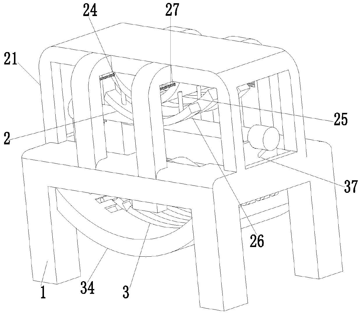
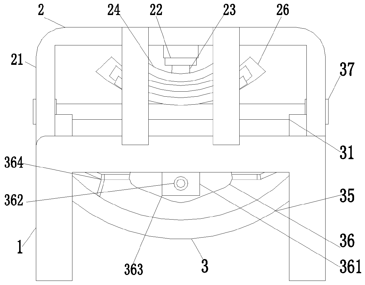
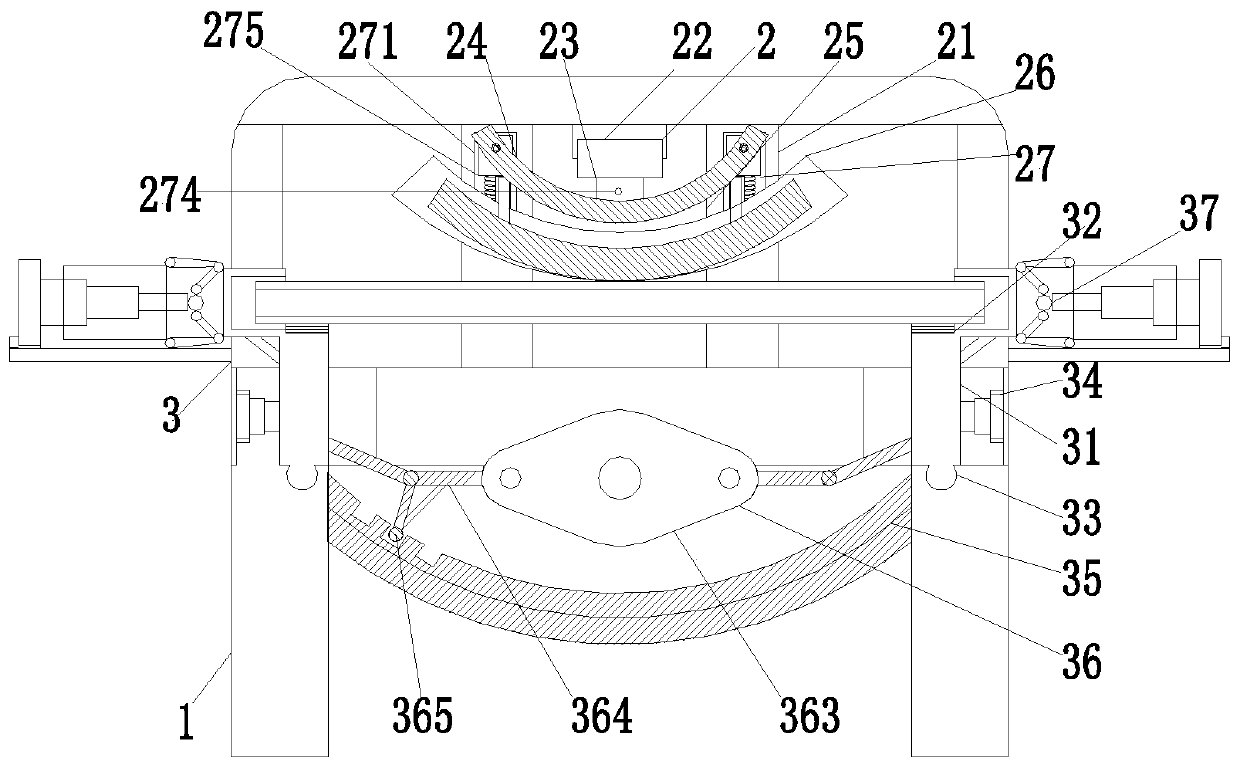
[0029] Such as Figure 1 to Figure 7 As shown, a steel structure metal pipe bending machine includes a support frame 1, a bending device 2 and a clamping device 3. The support frame 1 is in a U-shaped structure, and a bending device 2 is installed above the support frame 1. A clamping device 3 is arranged below the bending device 2 , and the clamping device 3 is installed on the support frame 1 .

[0030] The bending device 2 includes a U-shaped frame 21, a cylinder 22, a push rod 23, a bending plate 24, a connecting column 25, an arc-shaped pressing plate 26 and an adjustment mechanism 27, and the described U-shaped frame 21 is installed on the support frame 1 Above, a cylinder 22 is installed in the middle of the U-shaped frame 21, and the bottom...


PUM


Abstract

The invention relates to a bending machine for a steel structure metal pipe fitting. The bending machine comprises a supporting frame, a bending device and a clamping device, the supporting frame is of a U-shaped structure, the bending device is installed above the supporting frame, the clamping device is arranged below the bending device, and the clamping device is installed on the supporting frame. The bending machine for the steel structure metal pipe fitting can solve the problem that when an existing bending machine for a metal pipe fitting bends the metal pipe fitting, graded extrusion bending of the metal pipe fitting cannot be achieved, so that a straight pipe poor in bendability is prone to cracking and even the problem of breaking occurs during bending, the qualified rate of a finished bent pipe is affected, and the problem that when the existing bending machine clamps and fixes the metal pipe fitting, the clamping mechanism cannot be correspondingly adjusted along with position change of pipe fitting deformation, damage to a formed bent pipe is caused, the quality of the formed bent pipe is affected, metal pipe fittings with different diameters cannot be clamped and fixed, the formed bent pipe is unique in shape and single in diameter, and the use range is limited are solved.

Description

technical field [0001] The invention relates to the technical field of steel structure processing, in particular to a bending machine for steel structure metal pipe fittings. Background technique [0002] Steel structure building is a relatively common way in the field of construction at present. Steel structure buildings are more popular in bridges, houses and factories. Steel structure buildings need to use elbows for connection at special positions during the construction process. Steel structure buildings The processing quality of the bent pipe directly affects the overall quality of the steel structure building, so the processing of the steel structure bent pipe is also crucial to the overall building. [0003] At present, there are the following defects for the existing steel structure metal pipe fitting bending machine: 1. When the existing steel structure metal pipe fitting bending machine bends the metal pipe fitting, most of them use one-time extrusion to make the ...

Claims


Application Information

Patent Timeline
IPC IPC(8): B21D7/06B21D43/00
CPCB21D7/06B21D43/003
Inventor 张宇郭庆利郭庆营
Owner ANHUI DONGHAI MACHINE MFG CO LTD
Learn More