Material conveying mechanism with controller

A transmission mechanism and controller technology, applied to conveyors, conveyor objects, conveyor control devices, etc., can solve problems such as poor product quality, high labor intensity, and inability to transport as a whole

Pending Publication Date: 2020-08-04
安徽美格弗雷智能科技有限公司
View PDF0 Cites 0 Cited by
  • Summary
  • Abstract
  • Description
  • Claims
  • Application Information

AI Technical Summary

Problems solved by technology

[0002] At present, in the traditional workpiece processing and production process, some workers need to carry them, which makes the labor intensity high, and the work efficiency is low, and it is difficult to match the work progress of other equipment. When working, the equipment can only be stopped, Carrying out the product handling operation, the overall transportation cannot be carried out, which affects the working efficiency of the entire equipment, resulting in low production efficiency, poor safety, and poor product quality; most of the controllers of the existing multi-station material transmission mechanisms have the following problems, In an emergency, just stopping the work of the punching machine or the conveyor belt cannot achieve a real emergency stop, which may cause an accident and cause huge losses. The site environment is very complicated, and it is easy to generate error messages to the controller, causing the equipment Wrong action, causing serious consequences, without the ability of intelligent fault diagnosis

Method used


Image

  • Material conveying mechanism with controller
  • Material conveying mechanism with controller
  • Material conveying mechanism with controller

Examples


Embodiment Construction

[0022] The following will clearly and completely describe the technical solutions in the embodiments of the present invention with reference to the accompanying drawings in the embodiments of the present invention. Obviously, the described embodiments are only some, not all, embodiments of the present invention. All other embodiments obtained by persons of ordinary skill in the art based on the embodiments of the present invention belong to the protection scope of the present invention.

[0023] According to an embodiment of the present invention, a material transfer mechanism with a controller is provided.

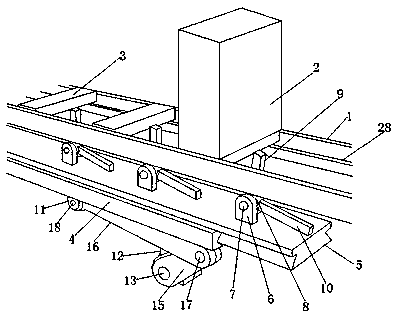
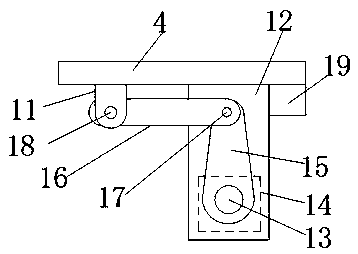
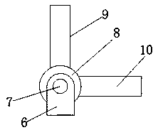
[0024] As shown in the figure, a material conveying mechanism with a controller according to an embodiment of the present invention includes a guide groove 1, and a placement box 2 is provided on one side of the guide groove 1, and a number of Work piece 3, the lower end of described guide groove 1 is provided with limiting groove 4, and movable plate 5 is arranged in des...


PUM


Abstract

The invention discloses a material conveying mechanism with a controller. The material conveying mechanism with the controller comprises a guide groove, a placing box is arranged at the upper end of one side of the guide groove, a plurality of workpieces are arranged in the placing box, a limiting groove is formed in the lower end of the guide groove, a movable plate is arranged in the limiting groove, a plurality fixing blocks are arranged at the upper end of the movable plate, a first rotating shaft is inserted between the two fixing blocks in a penetrating mode, a movable block is arrangedon the first rotating shaft and located between the two fixing blocks in a sleeve mode, a first movable rod is arranged on one side of the movable block, a second movable rod is arranged on the otherside of the movable block, a connecting block is arranged at the lower end of the movable plate, a fixing plate is arranged at the lower end of the limiting groove, a second rotating shaft is arrangedon one side of the lower end of the fixing plate in a penetrating mode, a motor is arranged on one end of the second rotating shaft, a rocker is arranged on the other end of the second rotating shaft, a connecting rod is arranged at the end, away from the second rotating shaft, of the rocker, the rocker is movably connected with the connecting rod through a third rotating shaft, and the end, awayfrom the third rotating shaft, of the connecting rod is movably connected with the connecting block through a fourth rotating shaft.

Description

technical field [0001] The invention relates to the field of controllers, in particular to a material conveying mechanism with a controller. Background technique [0002] At present, in the traditional workpiece processing and production process, some workers need to carry them, which makes the labor intensity high, and the work efficiency is low, and it is difficult to match the work progress of other equipment. When working, the equipment can only be stopped, Carrying out the product handling operation, the overall transportation cannot be carried out, which affects the working efficiency of the entire equipment, resulting in low production efficiency, poor safety, and poor product quality; most of the controllers of the existing multi-station material transmission mechanisms have the following problems, In an emergency, just stopping the work of the punching machine or the conveyor belt cannot achieve a real emergency stop, which may cause an accident and cause huge los...

Claims


Application Information

Patent Timeline
IPC IPC(8): B65G25/02B65G43/00
CPCB65G25/02B65G43/00
Inventor 薛文保
Owner 安徽美格弗雷智能科技有限公司
Why Eureka
Try Eureka