
Concrete vibrator auxiliary tool

An auxiliary tool and concrete technology, which is applied in the direction of construction, building structure, and building material processing, etc., can solve the problems of high vibration frequency, heavy weight of hand-held concrete vibrator, unsuitable for falling and moving, etc., to achieve easy operation and prevent tripping Inverted staff, the effect of regular wires

Active Publication Date: 2020-08-04
徐州启峰智能科技有限公司
View PDF11 Cites 0 Cited by
  • Summary
  • Abstract
  • Description
  • Claims
  • Application Information

AI Technical Summary

Problems solved by technology

[0002] In building concrete construction projects, concrete vibrators are often used to remove the air bubbles and gaps in the concrete, and the concrete vibrators are used to make the concrete stronger and firmer. However, due to the heavy weight and high vibration frequency of hand-held concrete vibrators, workers use a After the meeting, I lost my strength. For this reason, the Chinese utility model patent No. 2017202701607 discloses a concrete vibrator with a frame, which includes a handle on the top of the motor body, and a heat dissipation cover installed at the tail of the motor body. At the end of the output shaft of the motor main body, a butt joint connected with the plug-in middle stick flexible shaft is installed, and a protective tube is arranged outside the butt joint. The bottom of the motor main body is fixedly installed with a bottom support plate, and the bottom support The plate is welded and fixed on the bottom frame, and the bottom frame is vertically fixed with many vertical support rods, and the top of the vertical support rods is fixed with a top frame; the bottom frame and the top frame adopt a rectangular structure, and adopt an arc Transitioning each right angle, this patent can put the vibrator into the concrete through the setting of the frame. Because it is equipped with a frame, it is not suitable for falling to the ground and it is easy for workers to move; but workers still need to hold the vibrator and move it up and down to obtain greater depth of concrete vibration;

Method used


Image

  • Concrete vibrator auxiliary tool
  • Concrete vibrator auxiliary tool
  • Concrete vibrator auxiliary tool

Examples


Embodiment Construction

[0036] The technical solutions of the present invention will be further specifically described below through the embodiments and in conjunction with the accompanying drawings.

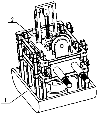
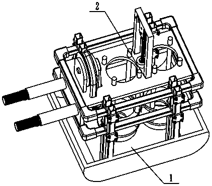
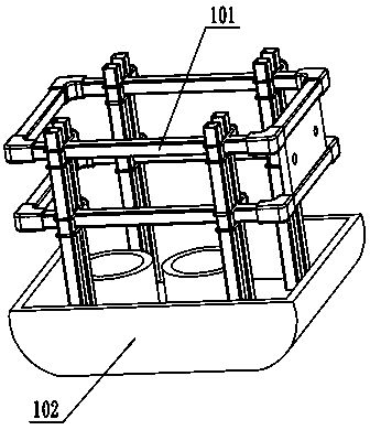
[0037] Examples, see figure 1 , figure 2 , image 3 , Figure 4 , Figure 5 , Figure 6 , Figure 7 , Figure 8 , Figure 9 , Figure 10 , Figure 11 , Figure 12 , Figure 13 , Figure 14 , Figure 15 As shown, a concrete vibrator auxiliary tool includes: a bracket part 1 and a placement part 2, and the placement part 2 is installed on the bracket part 1;

[0038] Described support part 1 comprises support frame 101, box body 102 and side plate 103, and box body 102 is fixedly installed under support frame 101; Side plate 103 is fixedly installed on the side of box body 102; on concrete, to reduce drag;

[0039] Described placement part 2 comprises supporting plate 204, pulley rope 206, block pulley 207, winding wheel 208, handle 2144 and connection shaft 224, and described supporting ...


PUM


Abstract

The invention discloses a concrete vibrator auxiliary tool. The concrete vibrator auxiliary tool comprises a support part and a containing part, and the containing part is installed on the support part; the support part comprises a support frame and a box body, and the box body is fixedly mounted below the support frame; the machine floats on concrete through the box body, so that the resistance is reduced; the containing part comprises a supporting plate, a pulley rope, a pulley block, a winding wheel and a grip, and the supporting plate is connected with the pulley rope; the pulley rope is mounted on the pulley block, and the supporting plate is hoisted through the pulley block so as to hoist the handheld concrete vibrator; the winding wheel is connected with the grip, the other end of the pulley rope is connected with the winding wheel; and the winding wheel is driven by rotating the grip so as to control the handheld concrete vibrator to move up and down. The front end and the rearend of the box body are arc-shaped, so that the resistance is reduced, and more labor can be saved when a worker pushes the box body.

Description

technical field [0001] The invention relates to the technical field of construction and concrete electric tools, in particular to a concrete vibrator auxiliary tool. Background technique [0002] In building concrete construction projects, concrete vibrators are often used to remove the air bubbles and gaps in the concrete, and the concrete vibrators are used to make the concrete stronger and firmer. However, due to the heavy weight and high vibration frequency of hand-held concrete vibrators, workers use a After the meeting, I lost my strength. For this reason, the Chinese utility model patent No. 2017202701607 discloses a concrete vibrator with a frame, which includes a handle on the top of the motor body, and a heat dissipation cover installed at the tail of the motor body. At the end of the output shaft of the motor main body, a butt joint connected with the plug-in middle stick flexible shaft is installed, and a protective tube is arranged outside the butt joint. The bo...

Claims


Application Information

Patent Timeline
Patent Type & Authority Applications(China)
IPC IPC(8): E04G21/08
CPCE04G21/08
Inventor 陈建军
Owner 徐州启峰智能科技有限公司
Learn More