
Involute helical gear helical angle modification optimization design method

A technology of optimized design and helix angle, applied in the field of mechanical dynamics, can solve the problems of reducing gear bearing capacity, gear tooth surface machining error, uneven gear tooth load distribution, etc., and achieve the effect of reducing the probability of eccentric load

Active Publication Date: 2020-08-04
BEIJING INSTITUTE OF TECHNOLOGYGY
View PDF7 Cites 4 Cited by
  • Summary
  • Abstract
  • Description
  • Claims
  • Application Information

AI Technical Summary

Problems solved by technology

These deformations will distort the helical line of the gear teeth. In addition, the machining error of the gear tooth surface will lead to uneven load distribution along the tooth width direction of the gear teeth, and the phenomenon of unbalanced load will occur. This state will reduce the bearing capacity of the gear and seriously will affect the reliable operation of the gear

Method used


Image

  • Involute helical gear helical angle modification optimization design method
  • Involute helical gear helical angle modification optimization design method
  • Involute helical gear helical angle modification optimization design method

Examples


Embodiment 1

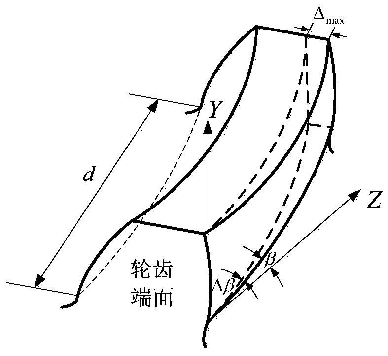
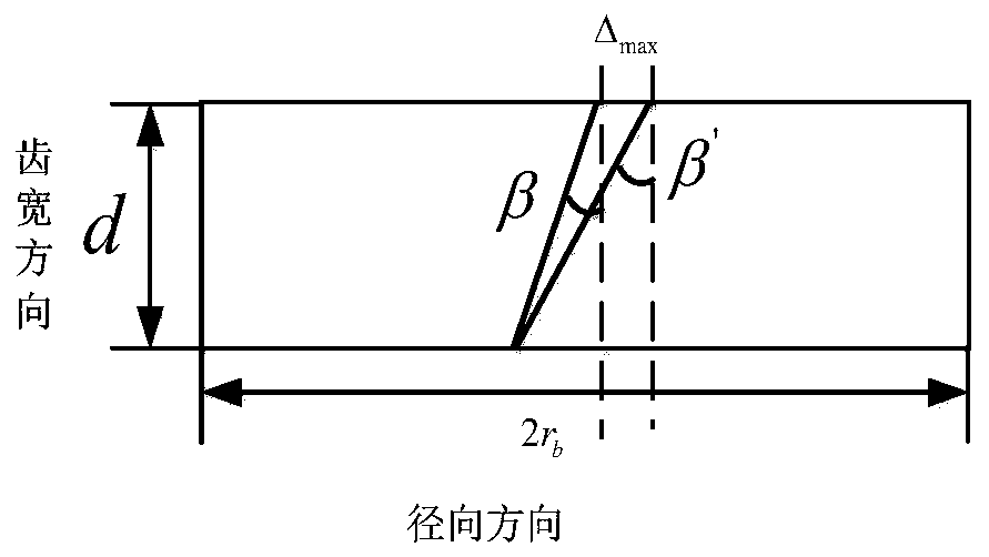
[0080] Using the method disclosed in the present invention, the maximum value of the maximum modification amount of the tooth width end face is Δ max =14μm, corresponding to the maximum helix angle modification amount Δ βmax =0°01'78”. For the helical gear pair with the parameters shown, two helical gears are modified at the same time, and the two helical gears adopt the same size and opposite direction to modify the helix angle of the helical gear pair. Among them, the value range of the maximum modification amount of the tooth width end face is [0μm, 14μm], and the value range of the corresponding tooth surface helix angle modification amount is [0°, 0°01'78”].

[0081] Under the steady-state working condition with an average input speed of 2000r / min and a load torque of 500Nm, according to the meshing stiffness calculation method, the maximum modification amount of the tooth width end face is within the range of [0μm, 14μm] for the meshing stiffness of the helical gear pair...


PUM


Abstract

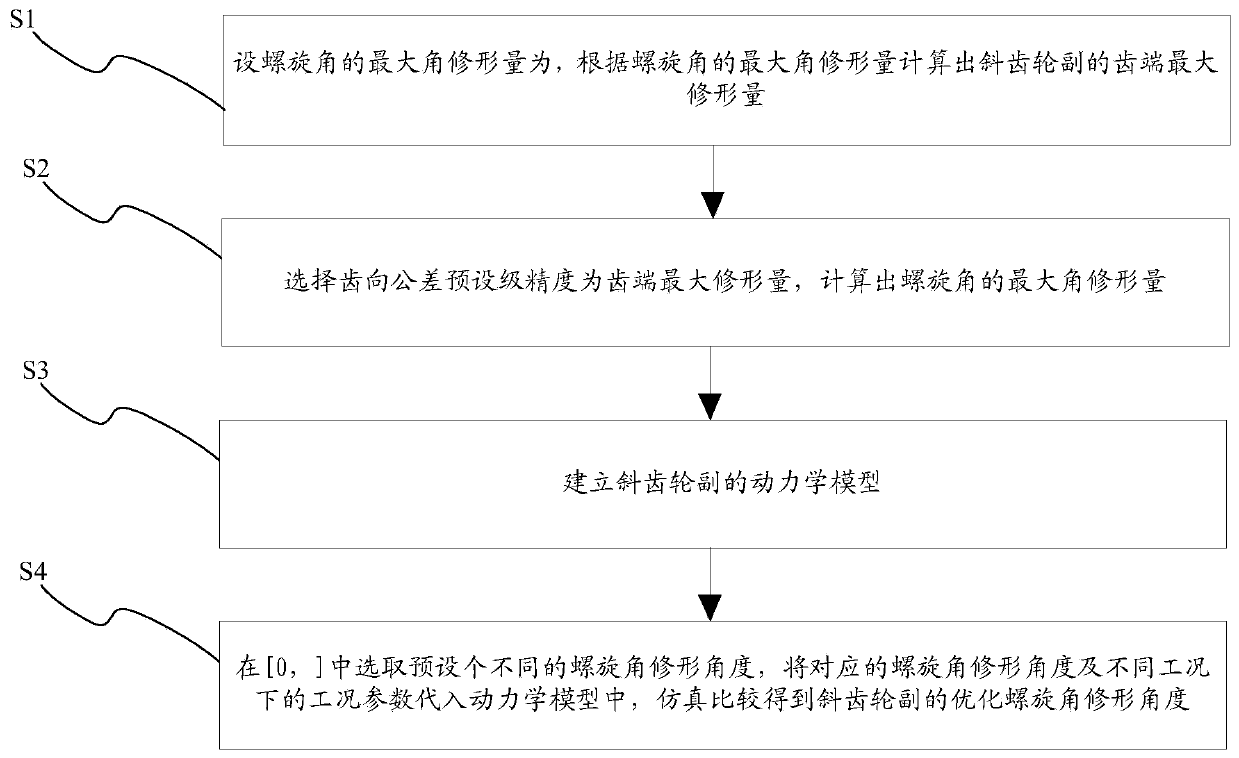
The invention provides an involute helical gear helical angle modification optimization design method which comprises the following steps: setting the maximum angle modification amount of a helical angle as delta beta, and calculating the maximum modification amount of a tooth end of a helical gear pair according to the maximum angle modification amount of the helical angle; selecting the tooth direction tolerance preset-level precision as the maximum modification amount of the tooth end, and calculating the maximum angle modification amount of the spiral angle; establishing a kinetic model ofthe helical gear pair; and selecting a preset number of different helical angle modification angles from [0, delta beta], substituting the corresponding helical angle modification angles and the working condition parameters under different working conditions into the kinetic model, and carrying out simulation comparison to obtain an optimized helical angle modification angle of the helical gear pair. The maximum modification amount of the helical angle is calculated, a preset number of different helical angle modification angles are selected from [0, delta beta] to be substituted into the kinetic model, the optimized helical angle modification angle of the helical gear pair is obtained through simulation and comparison, modification of the helical angle of the helical gear pair is achieved, and the probability of unbalance loading of the helical gear is reduced.

Description

technical field [0001] The invention relates to the technical field of mechanical dynamics, in particular to an optimal design method for helix angle modification of involute helical gears. Background technique [0002] In the actual meshing process of helical gears, due to the gear transmission system, including transmission shafts, bearings, boxes and other components, bending deformation and torsional deformation will occur under the action of load. These deformations will distort the helical line of the gear teeth. In addition, the machining error of the gear tooth surface will lead to uneven load distribution along the tooth width direction of the gear teeth, and the phenomenon of unbalanced load will occur. This state will reduce the bearing capacity of the gear and seriously It will affect the reliable operation of the gear. [0003] Therefore, how to reduce the probability of unbalanced load of the helical gear is a technical problem to be solved urgently by those s...

Claims


Application Information

Patent Timeline
Patent Type & Authority Applications(China)
IPC IPC(8): G06F30/17G06F30/20G06F119/14
CPCG06F30/17G06F30/20G06F2119/14
Inventor 刘辉严鹏飞张晨王珍
Owner BEIJING INSTITUTE OF TECHNOLOGYGY
Learn More