Portable wireless communication device, and information identification apparatus using portable wireless communication device
A wireless communication device, portable technology, applied to the record carrier used by the machine, the near-field transmission system using the transceiver, the antenna, etc., can solve the problem of resonance frequency change, etc., and achieve the effect of small quality deviation and low cost
- Summary
- Abstract
- Description
- Claims
- Application Information
AI Technical Summary
Problems solved by technology
Method used
Image


Examples
no. 1 approach
[0053] Hereinafter, a portable wireless communication device (hereinafter referred to as an IC tag) and an information identification device including an IC tag (tag) according to an embodiment of the present invention will be described.
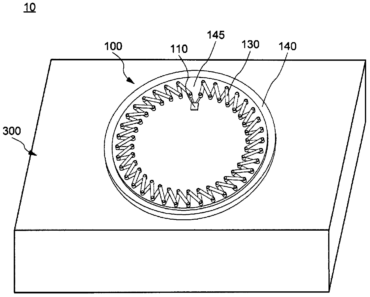
[0054] figure 1 is a schematic diagram of the information identification device 10 . The information identification device 10 includes an IC tag 100 and a reader / writer 300 .
[0055] (1-1, Composition of IC tags)
[0056] like figure 1 As shown, the IC tag 100 includes an IC chip 110 , a coil antenna (coil antenna) 130 , a supporting portion 140 and a substrate 145 . The IC chip 110 and the coil antenna 130 are disposed on the substrate 145 . The IC chip 110 and the coil antenna 130 are electrically connected locally.
[0057] The IC chip 110 is configured to generate a signal according to an instruction from a reader / writer 300 (described below). The signal is sent to the reader / writer 300 through the coil antenna 130 .
[0058] The...
no. 2 approach
[0103] In this embodiment, a description will be given of a portable wireless communication device having a coil antenna different in form from the first embodiment.
[0104] Figure 12 It is a top view of IC tag 100-1. In addition, in Figure 12 In the illustration, the electrode 137 and the through electrode 135 are omitted so that the electrode 133-1 of the coil antenna 130-1 of the IC tag 100-1 can be seen clearly, but the first electrode 133-1, the electrode 137 and the through electrode 135 are in contact with the second electrode 133-1. In one embodiment, they are connected in the same way to form one wiring as a whole.
[0105] like Figure 12 As shown, the electrode 133-1 includes an electrode 133-1-1 arranged on the outside and an electrode 133-1-2 arranged on the inside. At this time, the coil antenna 130-1 includes a loop antenna formed using the electrode 133-1-1 (sometimes referred to as the first antenna) and a loop antenna formed using the electrode 133-1-2...
no. 3 approach
[0117] In this embodiment, a portable wireless communication device including a coil antenna having a different form from the first and second embodiments will be described.
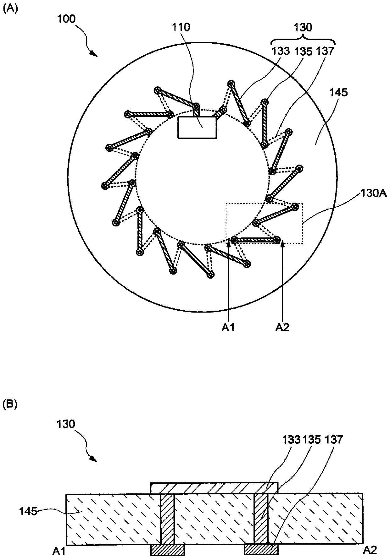
[0118] Figure 14 It is a plan view of the IC tag 100-3 and a cross-sectional view between A1-A2 of the coil antenna 130-3. exist Figure 14 In (A), the IC chip 110 is electrically connected to the coil antenna 130-3. The coil antenna 130-3 is configured in a loop.
[0119] like Figure 14 As shown in (B), between A1-A2, the coil antenna 130-3 includes a plurality of electrodes 151 (electrodes 151-1, electrode 151-1, electrode 151-2, electrode 151-3, electrode 151-4, electrode 151-5, electrode 151-6), multiple insulating layers 153 (insulating layer 153-1, insulating layer 153-2, insulating layer 153-3, insulating layer 153-4, insulating layer 153-5, insulating layer 153-6) and a plurality of through electrodes 155 (through electrode 155-1, through electrode 155-2, through electrode 155-3, through e...
PUM
 Abstract
Description
Claims
Application Information