
Oil filter replacement device

A technology of oil filter and installation cover, which is applied in the field of oil filter replacement device, which can solve the problems of complex operation of the equipment and inability to perform stable fixation, and achieve the effects of preventing sliding, stably fixing, and preventing excessive pulling

Active Publication Date: 2020-08-07
JIANGSU SHENGCAN AUTO PARTS
View PDF6 Cites 4 Cited by
  • Summary
  • Abstract
  • Description
  • Claims
  • Application Information

AI Technical Summary

Problems solved by technology

[0005] In order to overcome the shortcomings of the current method of oil filter replacement that cannot be stably fixed and the operation of the equipment is complicated, the technical problem is to provide an oil filter replacement device that can quickly unscrew and stably fix the oil filter

Method used


Image

  • Oil filter replacement device
  • Oil filter replacement device
  • Oil filter replacement device

Examples


Embodiment 1

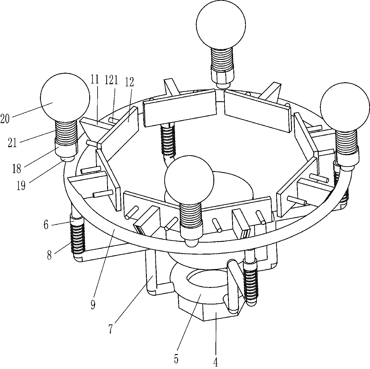
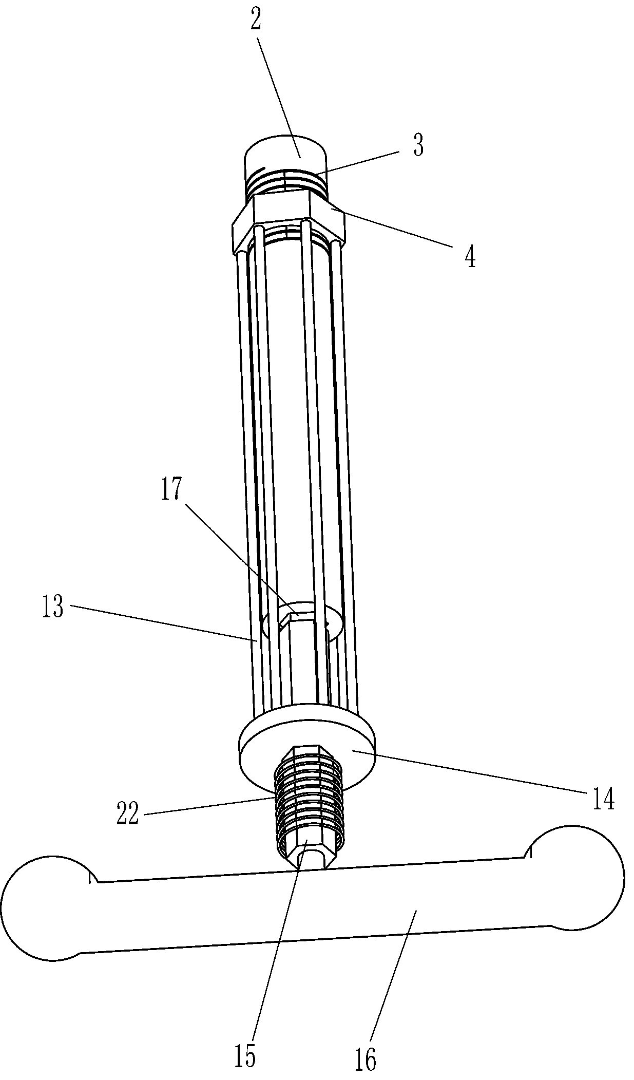
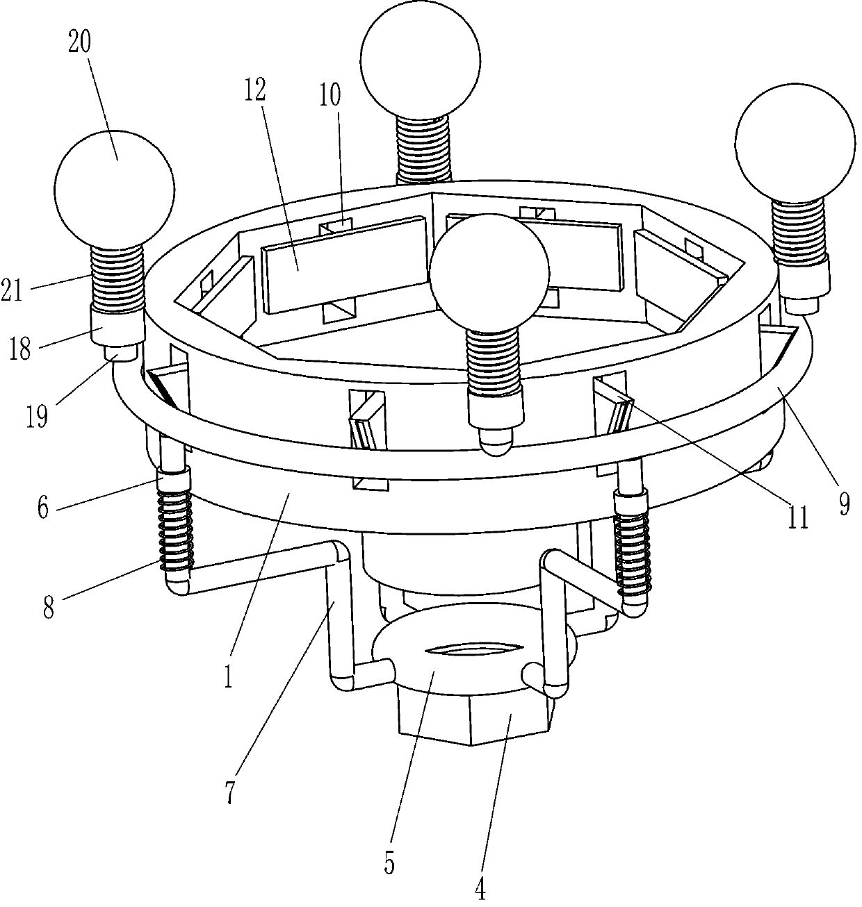
[0019] An oil filter replacement device such as Figure 1-4 As shown, it includes an installation cover 1, a first connecting rod 2, a fixed assembly and a power assembly. The installation cover 1 is used to install the entire device. The first connecting rod 2 is welded at the center of the bottom of the installation cover 1, and the fixed assembly is installed on the first The connecting rod 2 and the installation cover 1 are fixed by lifting, and the power assembly is installed on the lower part of the first connecting rod 2 to provide power by rotating.

[0020] Such as Figure 1-4 As shown, the fixed assembly includes a nut 4, a circular sleeve 5, a first guide sleeve 6, a connecting rod 7, a first spring 8, a ring 9, a wedge block 11, a pressure plate 12 and a guide rod 121, and the thread 3 is opened at the first The upper part of a connecting rod 2, the nut 4 is installed on the upper part of the first connecting rod 2 through the thread 3, the circular sleeve 5 is sl...

Embodiment 2

[0026] On the basis of Example 1, such as figure 1 , 3 As shown in and 4, it also includes a second guide sleeve 18, a slide bar 19, a plastic ball 20 and a second spring 21. There are four second guide sleeves 18, which are evenly installed on the upper part of the outer side of the installation cover 1 by screws. A slide bar 19 is slidably installed in the sleeve 18, the bottom end of the slide bar 19 is in contact with the top of the ring 9, a plastic ball 20 is installed on the top end of the slide bar 19, and a second spring 21 is connected between the second guide sleeve 18 and the plastic ball 20 .

[0027] Such as figure 1 with 2 As shown, it also includes a third spring 22 and a limit block 23, the third spring 22 is installed between the bottom of the connecting plate 14 and the bottom of the rhombus bar 15, and the bottom of the rhombus bar 15 is connected with two limit blocks 23, the limit block 23 is located above the connecting plate 14 and cooperates with i...


PUM


Abstract

The invention relates to a replacement device, in particular to an oil filter replacement device. The oil filter replacement device is used for quickly unscrewing and stably fixing an oil filter. Theoil filter replacement device comprises a mounting cover, a first connecting rod, a fixing component and a power component, wherein the mounting cover is used for being mounted on a whole device body;the first connecting rod is welded to the mounting cover; the fixing component is mounted between the first connecting rod and the mounting cover; and the power component is mounted on the first connecting rod and supplies power in a rotating mode. According to the oil filter replacement device, through cooperation of a thread and a nut, the oil filter can be quickly fixed and then dismantled; through cooperation of a rhombic rod and a rhombic hole, the oil filter can be quickly fixed and then dismantled; through cooperation of sliding rods and plastic balls, the oil filter can be dismantledand fixed more stably; and limiting blocks have a limiting function.

Description

technical field [0001] The invention relates to a replacement device, in particular to an oil filter replacement device. Background technique [0002] The oil filter, also known as the machine filter, is located in the engine lubrication system. The upstream of the machine filter is the oil pump, and the downstream is the parts of the engine that need to be lubricated. The machine filter filters out the harmful impurities in the engine oil from the oil pan, and supplies the clean engine oil to the crankshaft, connecting rod, camshaft, supercharger, piston ring and other moving pairs to lubricate, cool, and clean, thereby prolonging the life of the machine. The service life of these parts, when the oil filter is used for a long time, the oil filter needs to be replaced. [0003] The patent announcement number is CN209513169U, which discloses an oil filter replacement detection device, including a detection platform, a mounting frame is fixedly installed on the left end of t...

Claims


Application Information

Patent Timeline
Patent Type & Authority Applications(China)
IPC IPC(8): B25B27/00
CPCB25B27/00
Inventor 罗文翔
Owner JIANGSU SHENGCAN AUTO PARTS
Learn More