
3D printer controller and 3D printer control method

A technology of 3D printer and control method, which is applied to manufacturing auxiliary devices, processing data acquisition/processing, additive processing, etc. Effect

Inactive Publication Date: 2020-08-07
SHENZHEN ANYCUBIC TECH CO LTD
View PDF4 Cites 2 Cited by
  • Summary
  • Abstract
  • Description
  • Claims
  • Application Information

AI Technical Summary

Problems solved by technology

[0003] In view of the above-mentioned defects or deficiencies in the prior art, it is desired to provide a 3D printer controller and a 3D printer control method, which can solve the problem of low printing accuracy caused by the 3D printer in the prior art using only MCU as the main control

Method used


Image

  • 3D printer controller and 3D printer control method
  • 3D printer controller and 3D printer control method
  • 3D printer controller and 3D printer control method

Examples


Embodiment Construction

[0015] The application will be further described in detail below in conjunction with the accompanying drawings and embodiments. It should be understood that the specific embodiments described here are only used to explain related inventions, rather than to limit the invention. It should also be noted that, for ease of description, only parts related to the invention are shown in the drawings.

[0016] It should be noted that, in the case of no conflict, the embodiments in the present application and the features in the embodiments can be combined with each other. The present application will be described in detail below with reference to the accompanying drawings and embodiments.

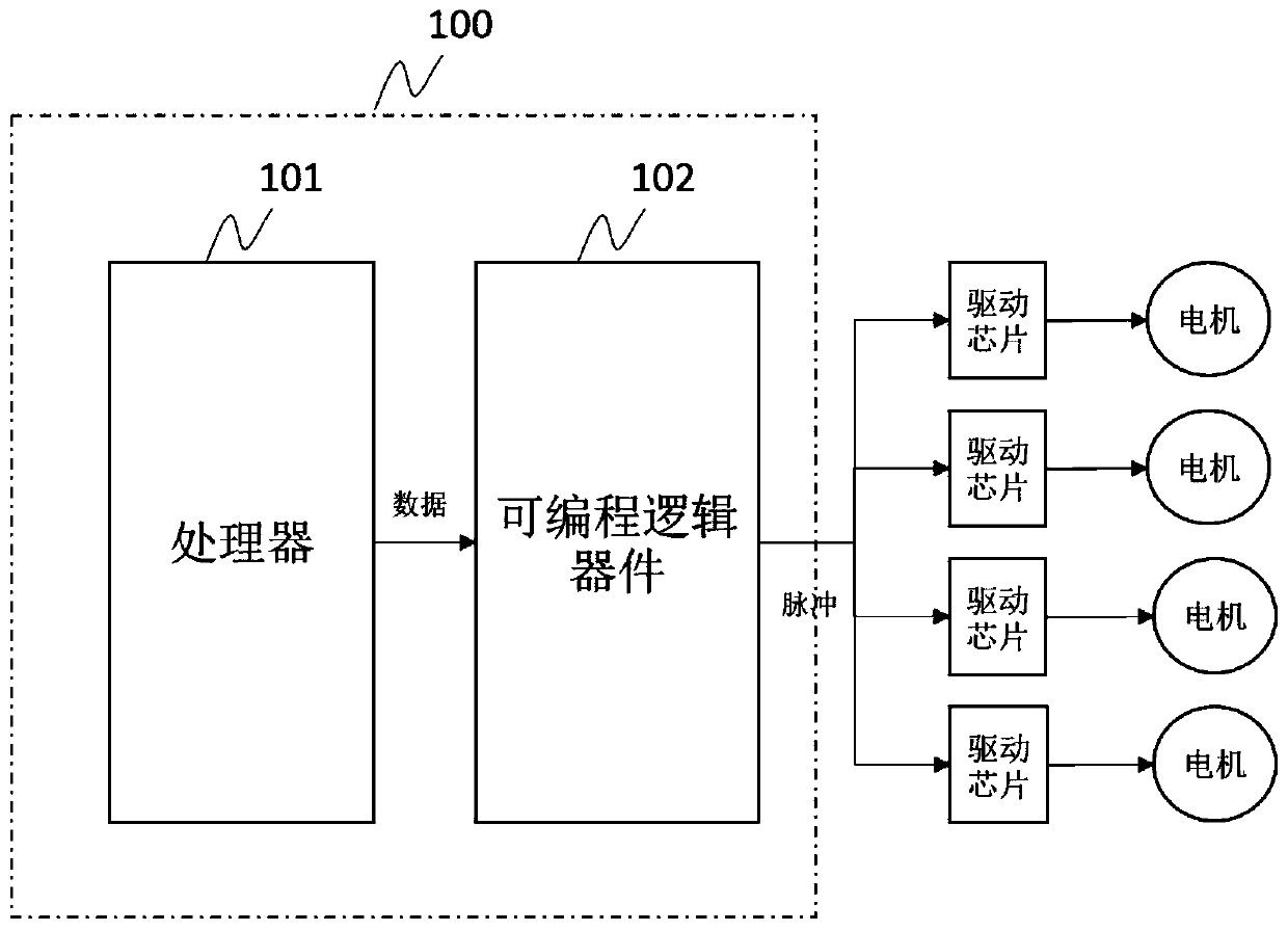
[0017] figure 1 It is a schematic diagram of a 3D printer controller in the embodiment of this application. A 3D printer controller 100 includes but not limited to a processor 101 and a programmable logic device 102 . Wherein, the processor 101 is configured to receive code data, generate motion...


PUM


Abstract

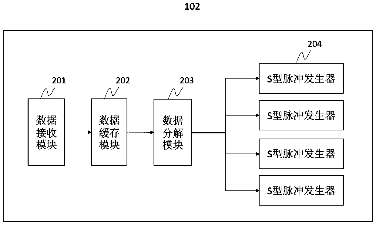
A 3D printer controller comprises a processor and a programmable logic device. The processor is used for receiving code data, generating movement block data based on the code data and sending the movement block data to the programmable logic device. The programmable logic device is used for receiving and temporally storing the movement block data, generating corresponding pulse signals based on the movement block data, and an S-shaped pulser is adopted as the programmable logic device. According to the 3D printer controller, the problem that in the prior art, only an MCU is adopted as master control, and consequently the printing precision is not high can be solved. The invention further discloses a 3D printer control method.

Description

technical field [0001] The present application generally relates to the technical field of 3D printers, and specifically relates to a 3D printer controller and a 3D printer control method. Background technique [0002] 3D printer is a device of rapid prototyping technology, which is composed of control components, mechanical components, and consumables. Among them, the control components play a decisive role in the accuracy and effect of the final model printing. Most of the existing 3D printers use MCU as the main control, and the MCU instructions are executed sequentially, while the movement of multiple axes of the 3D printer is executed simultaneously, resulting in time delay between the execution of different axes, which affects the printing accuracy . The motion control of existing 3D printers mostly uses T-shaped acceleration and deceleration, which will cause machine vibration and motor out of step. Contents of the invention [0003] In view of the above-mentione...

Claims


Application Information

Patent Timeline
Patent Type & Authority Applications(China)
IPC IPC(8): B29C64/393B33Y50/02
CPCB29C64/393B33Y50/02
Inventor 邓新桥欧阳欣
Owner SHENZHEN ANYCUBIC TECH CO LTD
Learn More