Guiding vehicle

A guide vehicle and wheel technology, applied in the field of guide vehicles, can solve the problems of unusable, poor obstacle-crossing ability, difficult processing, etc., and achieve the effect of strong adaptability, strong obstacle-crossing and climbing ability

Active Publication Date: 2020-08-07
GUANGDONG BOZHILIN ROBOT CO LTD
View PDF8 Cites 4 Cited by
  • Summary
  • Abstract
  • Description
  • Claims
  • Application Information

AI Technical Summary

Problems solved by technology

Most of the existing AGV trolleys that can move in all directions adopt omnidirectional wheels or Mecanum wheels to achieve all-round movement and rotation to meet industrial needs, but there are great limitations in actual use.
Mecanum wheels are expensive, difficult to process, and have a shorter service life than traditional rubber wheels; the structural design of the omnidirectional wheel determines that it cannot be used in places where there are many debris such as hair and dust particles. When the wheel is entangled by hair Or if it is stuck by particles, the force direction will deviate from the theoretical force direction, causing the AGV to move in an abnormal direction or rotate, and in severe cases, it will derail. It is used on terrain; two driving wheels plus two universal wheels, the universal wheels can be used as a support point, and there will not be much friction with the ground when the car rotates, but this design determines that the car's ability to overcome obstacles is very poor. When the universal wheel as a driven wheel encounters a large obstacle, the driving wheel may be suspended in the air. At this time, the AGV car loses its driving force and cannot move forward over the obstacle.

Method used


Image

  • Guiding vehicle
  • Guiding vehicle
  • Guiding vehicle

Examples


no. 1 example

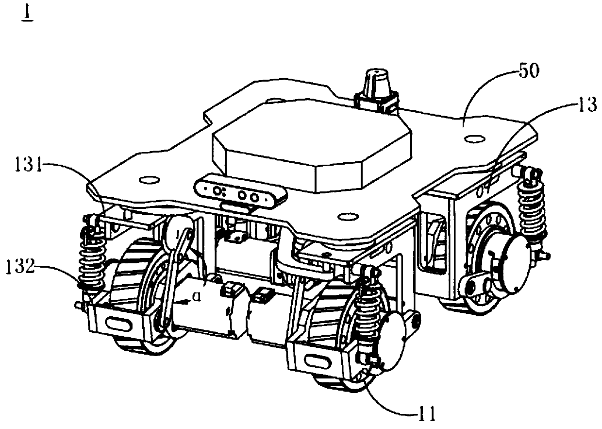
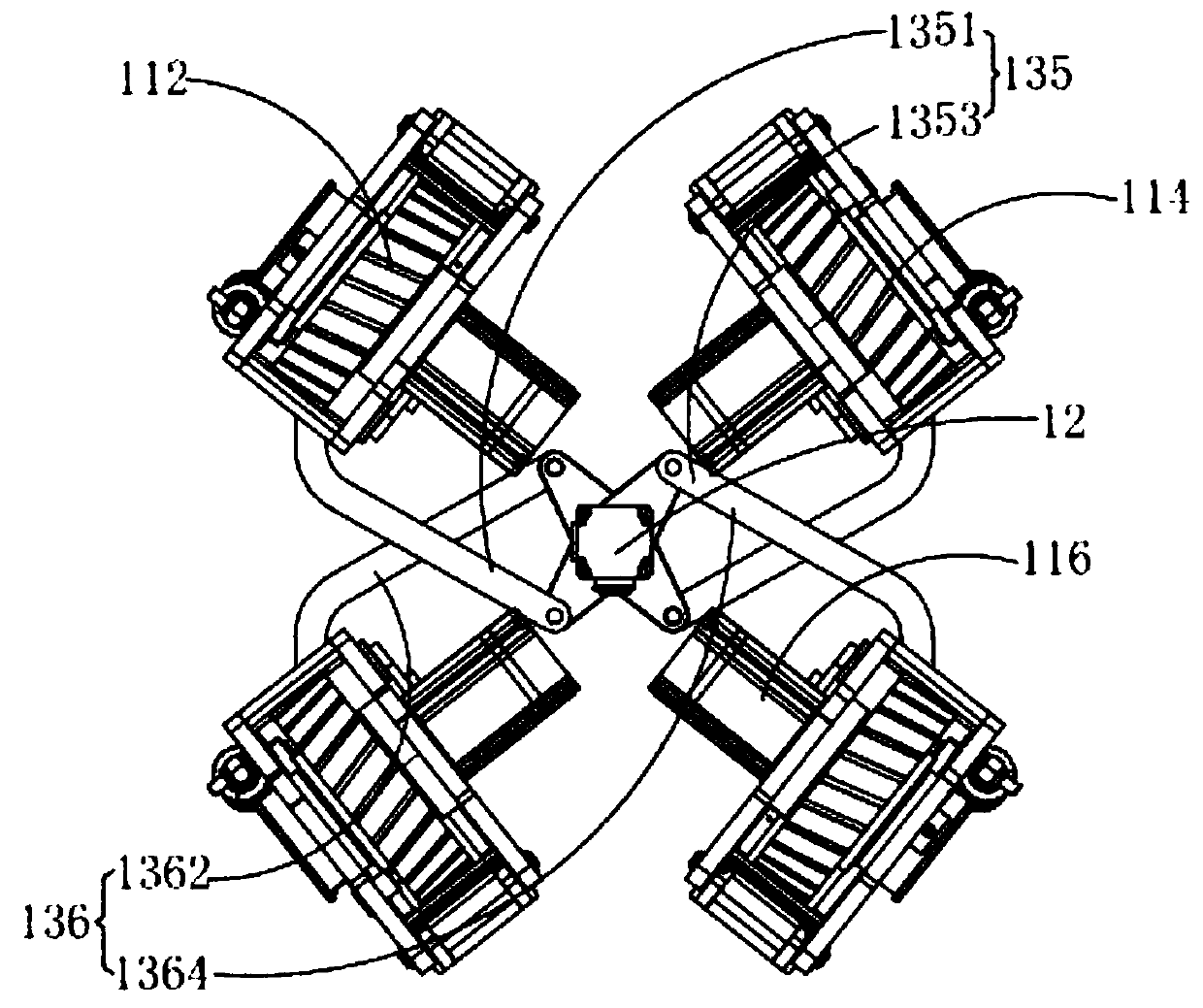
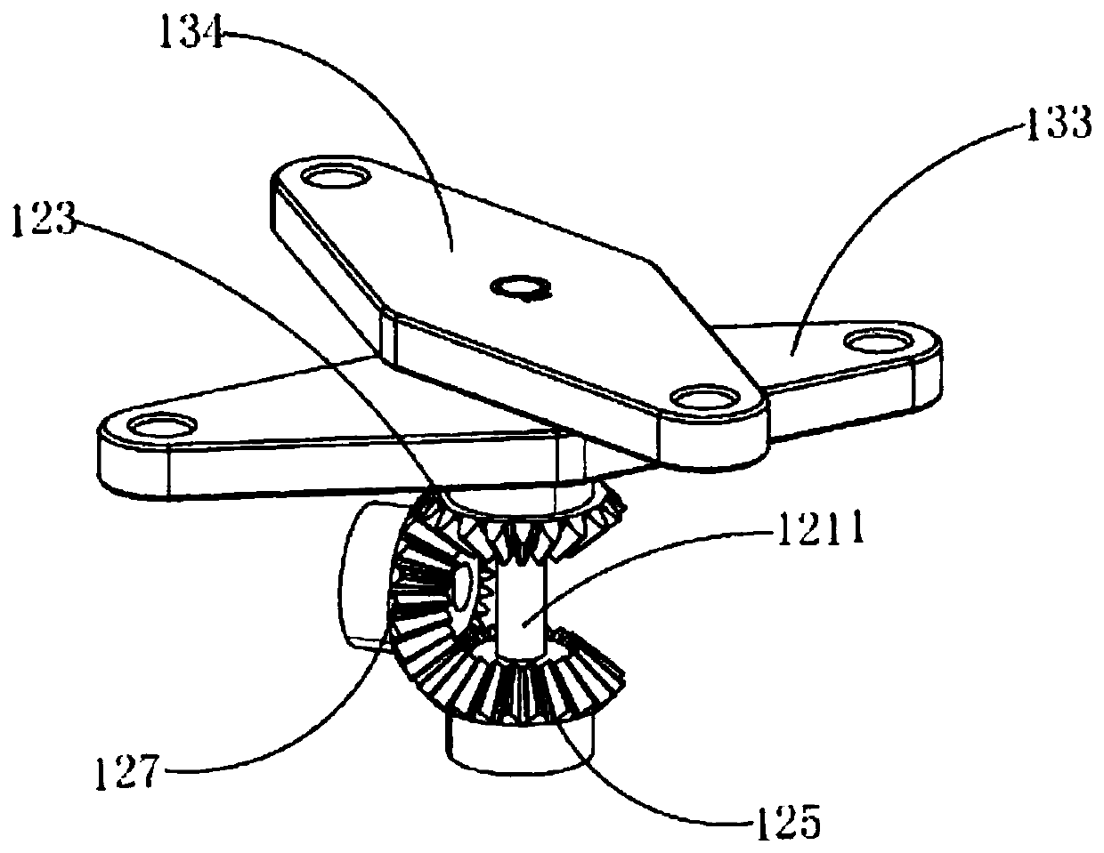
[0024] see figure 1 , figure 2 and image 3 , the present invention provides a guiding vehicle 1 , including a wheel system 11 , a first transmission mechanism 12 and a second transmission mechanism 13 . The wheel system 11 includes a first wheel set 112 and a second wheel set 114; the first transmission mechanism 12 includes a steering motor 121, a first gear 123 and a second gear 125, and the steering motor 121 drives the first gear 123 and the second gear 125 along the Rotate in the opposite direction; the second transmission mechanism 13 is mechanically connected between the first transmission mechanism 12 and the wheel system 11, the first gear 123 drives the first wheel set 112 to rotate through the second transmission mechanism 13, and the second gear 125 passes through the second The transmission mechanism 13 drives the second wheel set 114 to rotate.

[0025] see figure 2 and Figure 4 , in this embodiment, the first wheel set 112 includes a first driving wheel...

no. 2 example

[0052] see Figure 6 , Figure 7 and Figure 8 , different from the first embodiment, the second transmission mechanism 23 of the guide car 2 provided by the present application includes a guide rail 231, a first screw mandrel 232, a second screw mandrel 233, a first slider 234, and a second slider 235 , the first support block 236 and the second support block 237 . The first wheel set 212 includes a first driving wheel 2121 and a second driving wheel 2123, and the first wheel set 212 may be an omnidirectional wheel set. The second wheel set 214 includes a third drive wheel 2142 and a fourth drive wheel 2144 . The second wheel set 214 can be a differential drive wheel set, so that the center of rotation of the guide vehicle 2 can be set on the connecting line between the third drive wheel 2142 and the fourth drive wheel 2144, so that the lateral force during the correction process Changing from sliding friction to rolling friction overcomes the negative influence of latera...

no. 3 example

[0065] see Figure 10 and Figure 11 , different from the first embodiment, the first transmission mechanism 32 of the guide vehicle 3 provided by the present application does not include a third gear, and the first gear 323 and the second gear 325 mesh with each other, and the steering motor 321 and the first gear 323 Mechanically connected to drive the first gear 323 to rotate, and then to drive the second gear 325 to rotate.

[0066] The first gear 323 and the second gear 325 mesh with each other, and the first gear 323 and the second gear 325 are located on the same plane, that is, both are located between the first turning plate 333 and the second turning plate 334 . The first turning plate 333 is fixedly connected with the first gear 323, and the second turning plate 334 is fixedly connected with the second gear 325. Those skilled in the art can understand that the rotation directions of the two gears meshing with each other are opposite, so the first turning plate 333 ...


PUM


Abstract

The invention provides a guiding vehicle. The guiding vehicle comprises a wheel system, a first transmission mechanism and a second transmission mechanism. The wheel system comprises a first wheel setand a second wheel set. The first transmission mechanism comprises a steering motor, a first gear and a second gear, and the steering motor drives the first gear and the second gear to rotate in opposite directions; the second transmission mechanism is mechanically connected between the first transmission mechanism and the wheel system, the first gear drives the first wheel set to rotate throughthe second transmission mechanism, and the second gear drives the second wheel set to rotate through the second transmission mechanism. The steering motor drives the first gear and the second gear torotate in the opposite directions and drives the first wheel set and the second wheel set to rotate correspondingly, omnidirectional movement of the guiding vehicle is achieved, and the guiding vehicle is high in obstacle crossing and climbing capacity and high in adaptability to a construction site.

Description

technical field [0001] The invention relates to the technical field of construction machines, in particular to a guiding vehicle. Background technique [0002] Mobile AGV (Automatic Guided Vehicle, automatic guided vehicle) is used as a transportation tool in various fields. Most of the existing AGV trolleys capable of omnidirectional movement use omnidirectional wheels or Mecanum wheels to achieve omnidirectional movement and rotation to meet industrial needs, but there are relatively large limitations in actual use. Mecanum wheels are expensive, difficult to process, and have a shorter service life than traditional rubber wheels; the structural design of the omnidirectional wheel determines that it cannot be used in places where there are many debris such as hair and dust particles. When the wheel is entangled by hair Or if it is stuck by particles, the force direction will deviate from the theoretical force direction, resulting in abnormal movement direction or rotation ...

Claims


Application Information

Patent Timeline
Patent Type & Authority Applications(China)
IPC IPC(8): B62D5/04B62D3/12H02K7/116
CPCB62D5/0421B62D5/0463B62D3/12H02K7/1163
Inventor 周俊杰裴蓓蓓高奎沈健雷威周瑜陈祝权
Owner GUANGDONG BOZHILIN ROBOT CO LTD
Why Eureka
Try Eureka