Soft landing attitude and orbit integrated control method based on parallel variable thrust engine

A control method and engine technology, which are applied in the directions of aerospace vehicle landing devices, motor vehicles, and aerospace equipment, etc., can solve problems such as difficulty in meeting real-time requirements, and achieve the effects of avoiding computational burden, simple system, and easy online operation.

Active Publication Date: 2020-08-07
BEIJING INST OF CONTROL ENG
View PDF5 Cites 0 Cited by
  • Summary
  • Abstract
  • Description
  • Claims
  • Application Information

AI Technical Summary

Problems solved by technology

For detector control that requires fast calculation, real-time performance is difficult to meet the requirements

Method used


Image

  • Soft landing attitude and orbit integrated control method based on parallel variable thrust engine
  • Soft landing attitude and orbit integrated control method based on parallel variable thrust engine
  • Soft landing attitude and orbit integrated control method based on parallel variable thrust engine

Examples


Embodiment

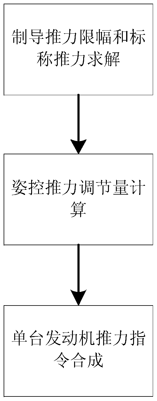
[0051] A soft landing attitude-orbit integrated control method based on parallel variable thrust engines, such as figure 1 As shown, the present invention includes three steps of guidance thrust limitation and nominal thrust solution, attitude control thrust adjustment amount calculation, and single engine thrust instruction synthesis.

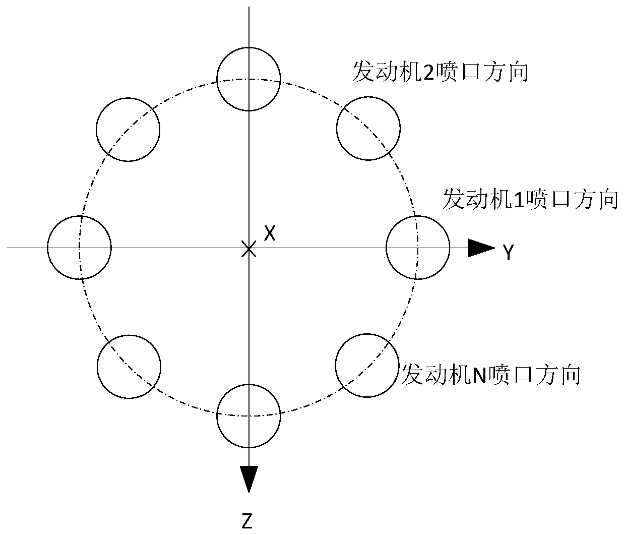
[0052] Such as figure 2 As shown, it is assumed that there are N engines installed on the bottom of the spacecraft ( figure 2 where N=8), all installed vertically (along the X axis). The installation positions of the N engines in the main system of the lander are respectively l 1 , l 2 ,...,l N , the direction of thrust action is p 1 ,p 2 ,...,p N , the output thrust of each engine is F 1 , F 2 ,...,F N ; x i 、y i ,z i is the coordinates of the i-th engine, and i is the ordinal number.

[0053] The installation position of each engine can be described by coordinates, namely

[0054] l i =[x i the y i z i ] T ,i=1,...,N ...


PUM


Abstract

The invention discloses a soft landing attitude and orbit integrated control method based on a parallel variable thrust engine, and belongs to the technical field of spacecraft guidance control, the method comprises the following steps of: S1, limiting the amplitude of guidance command thrust according to the total variable thrust capacity range of an engine unit, and calculating the minimum normsolution of the command thrust of each engine by utilizing the limited guidance command thrust to serve as the nominal command thrust of each engine; S2, according to the instruction torque, determining the final adjustment amount of each engine on the basis of the nominal instruction thrust; and S3, determining a thrust instruction of each engine according to the nominal instruction thrust of each engine in the S1 and the final adjustment amount of each engine on the basis of the nominal instruction thrust in the S2.

Description

technical field [0001] The invention relates to an attitude-orbit integrated control method for soft landing based on parallel variable thrust engines, belonging to the technical field of spacecraft guidance and control. Background technique [0002] The soft landing process of extraterrestrial objects requires the use of variable thrust engines to meet the complex guidance laws for different thrust requirements at different stages. When the scale of the detector is large, it is very difficult to develop a single high-thrust variable-thrust engine for a specific task. Providing the thrust required for guidance is an effective solution. [0003] When multiple engines work at the same time, the thrust of each engine is usually adjusted synchronously. However, due to the inconsistency of the thrust deviation of each engine, coupled with the deviation of the installation and the deviation of the detector's center of mass, disturbance torque will inevitably be generated. At this...

Claims


Application Information

Patent Timeline
Patent Type & Authority Applications(China)
IPC IPC(8): B64G1/24B64G1/26B64G1/62
CPCB64G1/242B64G1/26B64G1/62B64G1/245
Inventor 李骥关轶峰胡锦昌张洪华
Owner BEIJING INST OF CONTROL ENG
Why Eureka
Try Eureka