Automatic lifting platform

An automatic lifting and platform technology, applied in the direction of lifting frame, lifting device, etc., can solve the problems of complex structure of hydraulic drive device or pneumatic drive device, low degree of automation and stability, and difficulty in rising at a constant speed, achieving small structure, Improved stability, stable and controllable lifting speed

Inactive Publication Date: 2020-08-07
WUYI UNIV
View PDF5 Cites 0 Cited by
  • Summary
  • Abstract
  • Description
  • Claims
  • Application Information

AI Technical Summary

Problems solved by technology

[0002] In the industrial field, the lifting platform is a common lifting device, such as the common hydraulic lifting platform or pneumatic lifting platform, but the structure of the hydraulic driving device or pneumatic driving device is complicated, the noise is loud, and it is difficult to achieve stable and uniform lifting. and less stable

Method used


Image

  • Automatic lifting platform
  • Automatic lifting platform

Examples


Embodiment Construction

[0020] This part will describe the specific embodiment of the application in detail. The preferred embodiment of the application is shown in the accompanying drawings. Each technical feature and overall technical solution of the application, but it should not be understood as a limitation on the protection scope of the application.

[0021] In order to make the purpose, technical solution and advantages of the present application clearer, the present application will be further described in detail below in conjunction with the accompanying drawings and embodiments. It should be understood that the specific embodiments described here are only used to explain the present application, not to limit the present application.

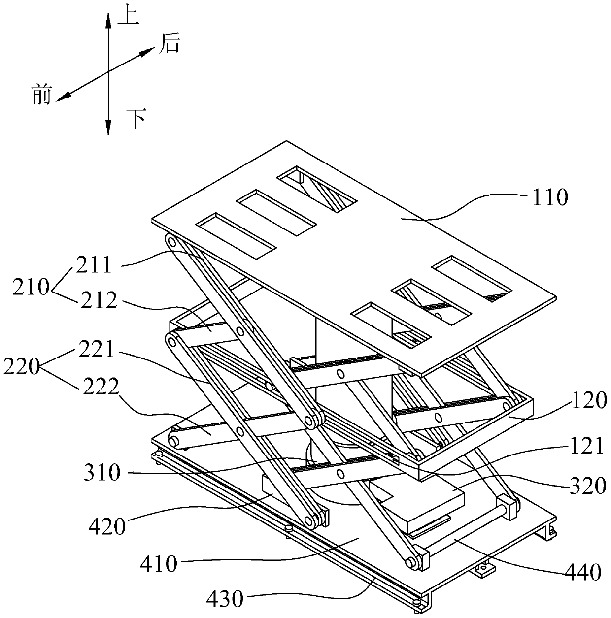
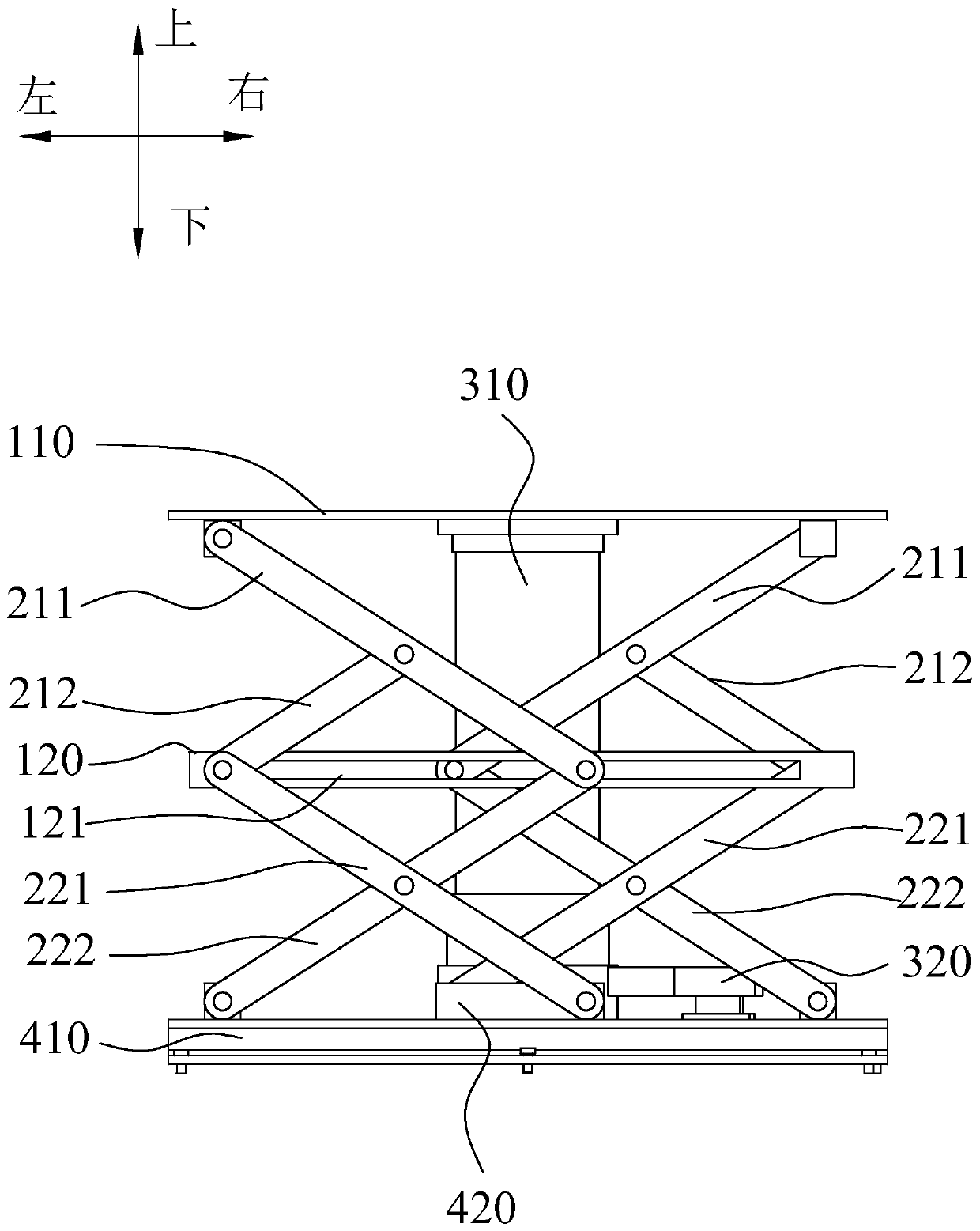
[0022] In the description of the present application, it should be understood that the orientation descriptions, such as up, down, front, back, left, right, etc. indicated orientations or positional relationships are based on the orientations or positional rel...


PUM


Abstract

The invention discloses an automatic lifting platform. The platform comprises a platform body and a base, scissor fork parts are arranged on the front side and the rear side between the platform bodyand the base, the scissor fork parts comprise upper scissor fork arms and lower scissor fork arms, one ends of the upper scissor fork arms and one ends of the lower scissor fork arms are rotationallyconnected to a connecting frame, the other ends of the upper shear fork arms are rotationally connected with the platform body, the other ends of the lower shear fork arms are rotationally connected with the base, and the stability of the platform in the lifting process is improved through the two sections of shear fork arms distributed up and down; the platform further comprises a spiral liftingdevice, the two ends of the spiral lifting device are fixedly connected to the base and the platform body respectively, and the lifting speed of the spiral lifting device is stable and controllable sothat constant-speed lifting can be conveniently achieved; and the platform further comprises a servo driver used for driving the spiral lifting device to stretch out and draw back, the servo driver is electrically connected with the spiral lifting device, and the control precision of the servo driver is high so that the stability of the lifting platform can be improved.

Description

technical field [0001] The present application relates to the field of automation equipment, in particular to an automatic lifting platform. Background technique [0002] In the industrial field, the lifting platform is a common lifting device, such as the common hydraulic lifting platform or pneumatic lifting platform, but the structure of the hydraulic driving device or pneumatic driving device is complex, the noise is loud, and it is difficult to achieve a stable and uniform rise. and lower stability. Contents of the invention [0003] This application aims to solve one of the technical problems in the related art at least to a certain extent. For this reason, the application proposes an automatic lifting platform, which can effectively improve the stability and automation of the lifting platform. [0004] In the first aspect, the embodiment of the present application provides an automatic lifting platform, including a platform and a base, and scissors are provided on...

Claims


Application Information

Patent Timeline
Patent Type & Authority Applications(China)
IPC IPC(8): B66F7/06B66F7/28
CPCB66F7/0666B66F7/28
Inventor 王宏民陈毅张密谢啊奋叶浩槐
Owner WUYI UNIV
Why Eureka
Try Eureka