A garden artificial lawn laying device

A technology of artificial turf and laying device, which is applied in roads, buildings, road repairs, etc. It can solve the problems of limited turf size and inability to lay turf at one time, and achieve the effect of accurate laying position, normal laying and avoiding waste

Active Publication Date: 2021-11-05
中建福建建设有限公司
View PDF0 Cites 0 Cited by
  • Summary
  • Abstract
  • Description
  • Claims
  • Application Information

AI Technical Summary

Problems solved by technology

[0002] In the process of laying artificial turf, the rolled artificial turf is very heavy due to the soil. If the lawn is too heavy, the lawn will not open with the rotation of the shaft during the laying process. The inventor found that The size of the lawn that the lawn laying devices on the market can carry is limited, and it is not possible to lay too long lawn at one time

Method used


Image

  • A garden artificial lawn laying device
  • A garden artificial lawn laying device
  • A garden artificial lawn laying device

Examples


specific Embodiment approach 1

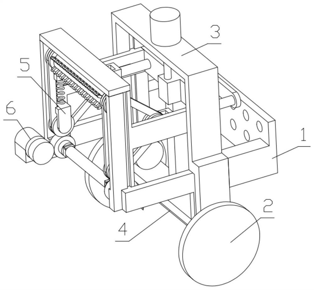
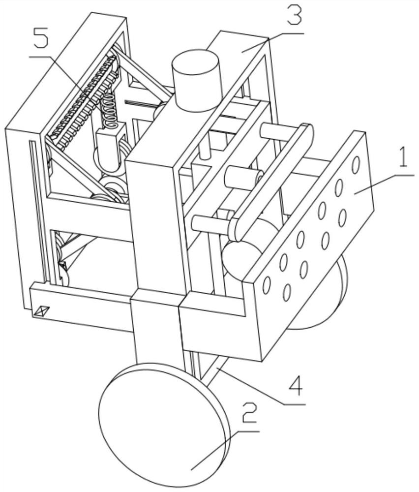
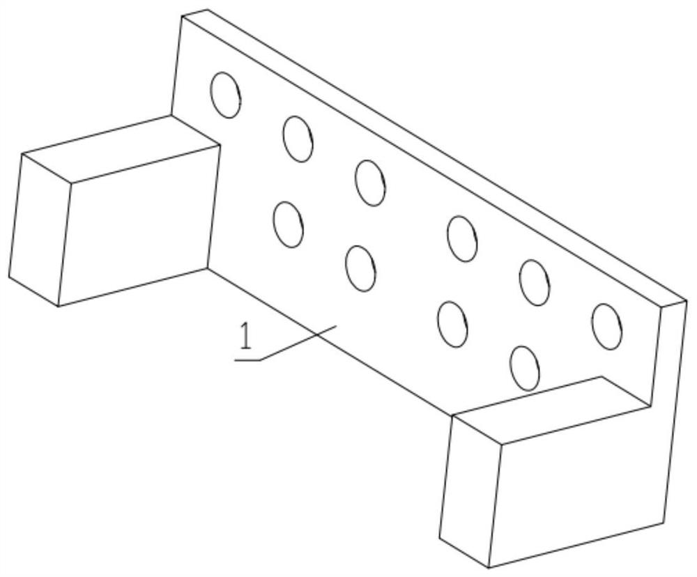
[0034] Combine below Figure 1-15 Description of this embodiment, a garden artificial lawn laying device, including an agricultural locomotive connecting plate 1, a moving wheel 2, and a device mounting frame 3, the agricultural locomotive connecting plate 1 is fixedly mounted on the device mounting frame 3, and the moving wheel 2 is rotatably mounted on the device On the installation frame 3 , the cutting mechanism 4 is installed on the device installation frame 3 , and the unwinding mechanism 5 is installed on the device installation frame 3 .

specific Embodiment approach 2

[0035] Combine below Figure 1-15 This embodiment will be described. This embodiment will further explain the first embodiment. The device installation frame 3 includes a frame main body 3-1, a lift adjustment motor 3-2, and a threaded column 3-3. The lift adjustment motor 3-2 passes through the The through hole provided on the frame main body 3-1 is fixedly installed on the frame main body 3-1, and one end of the threaded post 3-3 is rotatably installed on the groove provided on the frame main body 3-1, and the other end of the threaded post 3-3 One end is fixedly installed on the output end of the lifting adjustment motor 3-2, and the gear motor 6 is fixedly installed on the unwinding mechanism 5, and the lifting adjustment motor 3-2 is started to rotate the threaded column 3-3, and then the connecting beam 5-2 Driving the unwinding mechanism 5 to move downward as a whole will shorten the distance between the lawn roll and the ground, so that the lawn can be laid accurately....

specific Embodiment approach 3

[0036] Combine below Figure 1-15Describe this embodiment, this embodiment will further explain the second embodiment, the cutting mechanism 4 includes a threaded rod 4-1, a cutter 4-2, a threaded moving part 4-3, a driven gear 4-4, a driving Gear 4-5, motor 4-6, motor 4-6 passes through the through hole provided on the frame main body 3-1 and is fixedly installed on the frame main body 3-1, and driving gear 4-5 is fixedly installed on the motor 4-6 output end, the driving gear 4-5 meshes with the driven gear 4-4, the driven gear 4-4 is fixedly installed on one end of the threaded rod 4-1, and the other end of the threaded rod 4-1 is rotatably mounted on the frame main body 3-1 On the groove provided above, the threaded rod 4-1 is threadedly connected with the threaded moving part 4-3, the threaded moving part 4-3 is fixedly equipped with a cutter 4-2, and the threaded moving part 4-3 is slidably installed on the frame main body 3 On the groove provided on -1, since the lawn ...


PUM


Abstract

The invention relates to a garden device, more specifically a garden artificial turf laying device, comprising an agricultural locomotive connecting plate, a moving wheel, and a device installation frame, the agricultural locomotive connecting plate is fixedly installed on the device installation frame, and the moving wheel is rotatably installed On the device installation frame, the cutting mechanism is installed on the device installation frame, and the unwinding mechanism is installed on the device installation frame. The device can load a long artificial lawn, and is equipped with an auxiliary lawn laying mechanism. The mechanism can cut the lawn arbitrarily, which is convenient for splicing between lawns.

Description

technical field [0001] The invention relates to a garden device, in particular to a garden artificial lawn laying device. Background technique [0002] In the process of laying artificial turf, the rolled artificial turf is very heavy due to the soil. If the lawn is too heavy, the lawn will not open with the rotation of the shaft during the laying process. The inventor found that The size of the lawn that the lawn laying device on the market can carry is limited, and it is not possible to lay too long lawn at one time. Contents of the invention [0003] The technical problem mainly solved by the present invention is to provide a garden artificial turf laying device, the device can load a long artificial turf, and is equipped with an auxiliary lawn laying mechanism, and the device is also equipped with a cutting mechanism, which can cut the lawn arbitrarily, which is convenient Splicing between lawns. [0004] The purpose of the present invention is achieved through the f...

Claims


Application Information

Patent Timeline
Patent Type & Authority Patents(China)
IPC IPC(8): E01C19/52
CPCE01C19/522
Inventor 王晓烽南宇峰
Owner 中建福建建设有限公司
Why Eureka
Try Eureka