
A municipal road surface isolation guardrail cleaning device

A cleaning device and guardrail technology, applied in road cleaning, cleaning methods, construction, etc., can solve the problems that both sides of the guardrail cannot be cleaned at the same time, it is not easy to promote and implement, and the guardrail cannot be cleaned, etc., so as to achieve strong applicability, avoid dead ends, and improve The effect of cleaning efficiency

Active Publication Date: 2021-09-03
安徽艺林环境工程有限公司
View PDF15 Cites 0 Cited by
  • Summary
  • Abstract
  • Description
  • Claims
  • Application Information

AI Technical Summary

Problems solved by technology

The structure of the equipment is complicated, and it cannot clean both sides of the guardrail at the same time, which makes it impossible to clean the guardrail on one side of the road, which is not easy to promote and implement

Method used


Image

  • A municipal road surface isolation guardrail cleaning device
  • A municipal road surface isolation guardrail cleaning device
  • A municipal road surface isolation guardrail cleaning device

Examples


Embodiment 1

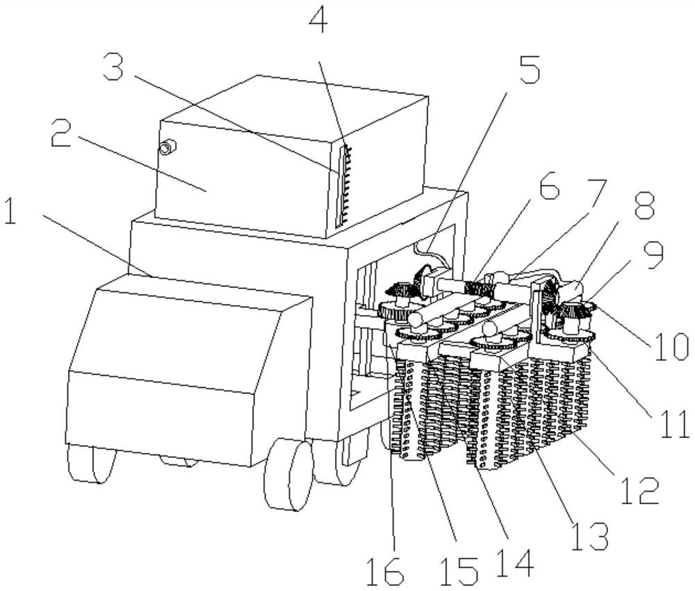
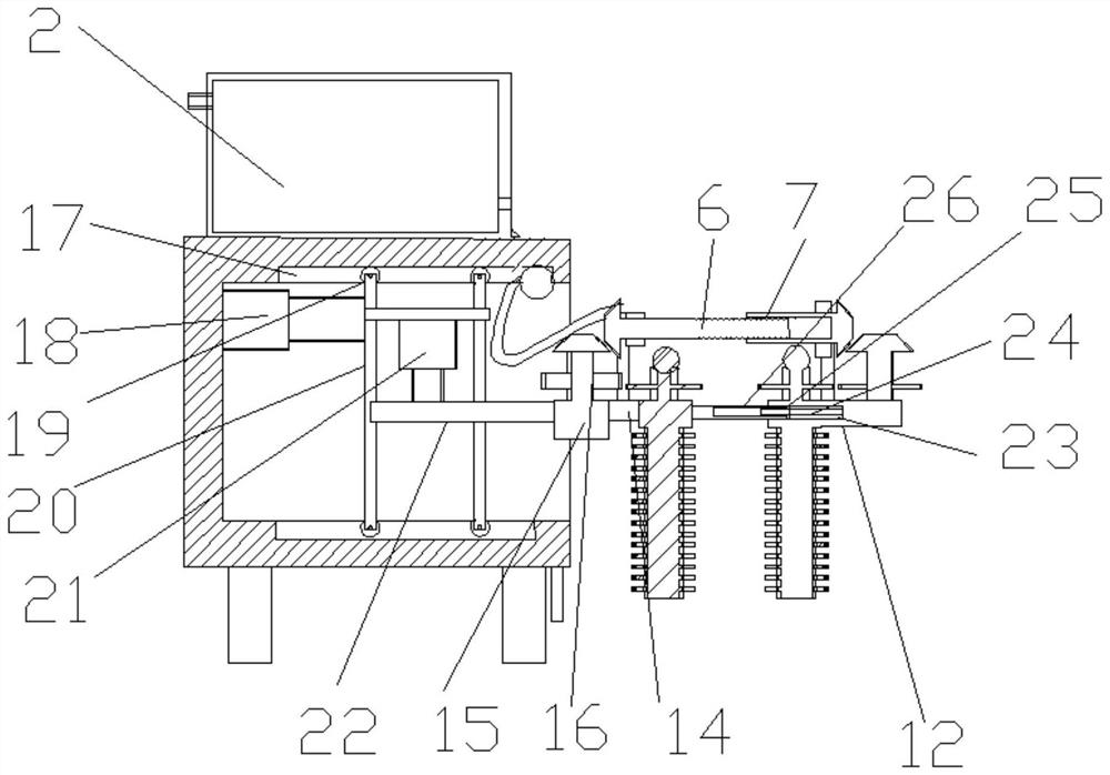
[0026] see Figure 1-4 , a municipal road surface isolation guardrail cleaning device, including a compartment 1, a brush roller 13 and a first mounting frame 12. The interior of the compartment 1 is slidingly provided with a horizontal moving frame 20, the inner side wall of the compartment 1 is fixedly connected to one end of the first hydraulic rod 18, and the other end of the first hydraulic rod 18 is fixedly connected to the horizontal moving frame 20. Telescoping, drive the horizontal moving frame 20 to slide inside the compartment 1, the top and bottom of the horizontal moving frame 20 are rotated and provided with pulleys 19, and the upper and lower sides of the horizontal moving frame 20 are provided with sliding grooves 17 and pulleys 19 at the inner bottom and top of the compartment 1 Nested inside the sliding groove 17, thereby reducing the frictional force between the horizontal moving frame 20 and the carriage 1, and making the sliding of the horizontal moving fr...

Embodiment 2

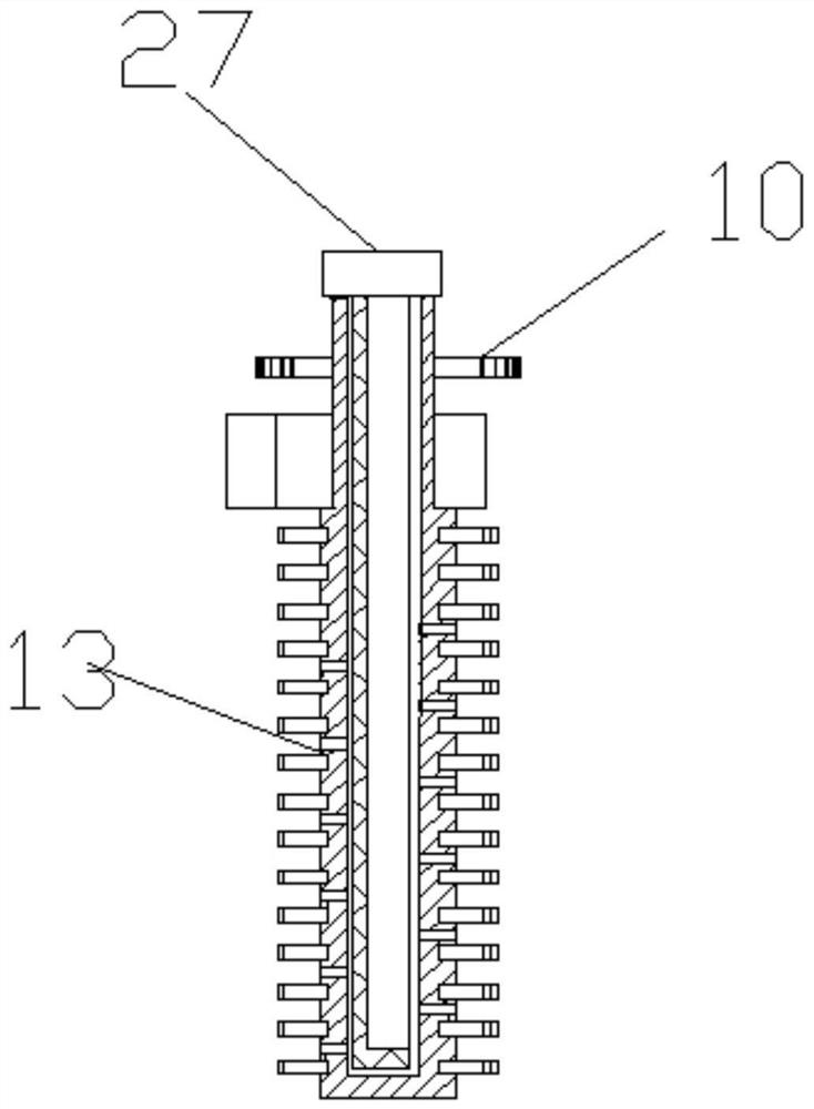
[0031] On the basis of Embodiment 1, a water tank 2 is arranged on the compartment 1, and a water pump is fixedly arranged inside the compartment 1. The water tank 2 communicates with the water pump, and the water pump communicates with the water pipe 8 through the hose 5. The brush roller 13 is a hollow structure and is provided with a spray The water hole, the internal rotation of the brush roller 13 is provided with an inner sleeve 27, the inner sleeve 27 is a C-shaped structure in cross section and the opening is towards the guardrail position, and the water pipe 8 is fixedly communicated with the inner sleeve 27. Under the action of the water pump, the water inside the water tank 2 enters the inside of the brush roller 13 and sprays out from the spray hole, thereby facilitating the cleaning of the guardrail. Under the action of the inner casing 27, the water is sprayed toward the guardrail in a directional manner, which prevents the water from spraying in other directions,...


PUM


Abstract

The invention relates to the technical field of municipal equipment, and specifically discloses a municipal road surface isolation guardrail cleaning device, which includes a carriage, a brush roller and a first installation frame. The hydraulic rod is connected to the horizontal moving frame, and the horizontal moving frame is connected with the lifting frame through the second hydraulic rod, and the outer end of the lifting frame is fixedly connected with the second mounting frame and the first mounting frame, and the second mounting frame and the first mounting frame A number of brush rollers are installed on the upper rotation, and the brush rollers are coaxially fixedly connected with transmission gears, wherein two adjacent transmission gears mesh with each other. There is a cover rod, and the ends of the screw rod and the cover rod are connected on the connecting rod and the motor through the steering gear. The invention has the advantages of simple structure, convenient operation, high cleaning efficiency, strong applicability, low cleaning cost and easy popularization and implementation.

Description

technical field [0001] The invention relates to the technical field of municipal equipment, in particular to a cleaning device for isolation guardrails on municipal road surfaces. Background technique [0002] Guardrail --- here refers to the industrial "guardrail". Guardrails are mainly used for the protection and protection of personal safety and equipment and facilities in residences, highways, commercial areas, public places and other occasions. Guardrails can be seen everywhere in our lives. Depending on the height of the guardrail, the price per meter of length will also vary. The guardrail is usually made of steel, such as: stainless steel, round steel pipe, square steel pipe or profiled steel plate, iron wire. Surface treatment process: automatic electrostatic powder spraying (that is, plastic spraying) or painting. In recent years, plug-in and assembled guardrails made of aluminum alloy have become more popular. The existing cleaning of bridge guardrails for tr...

Claims


Application Information

Patent Timeline
Patent Type & Authority Patents(China)
IPC IPC(8): E01H1/00
CPCE01H1/005
Inventor 李锦春
Owner 安徽艺林环境工程有限公司
Learn More