Interlock control apparatus

A technology of interlocking control and control device, applied in the direction of electrical program control, general control system, control/regulation system, etc., can solve the problems of complicated wiring, difficulty in analyzing its causes, complicated interlocking control conditions, etc. The effect of reducing the number of signals, reducing wiring, and simplifying the configuration

Inactive Publication Date: 2009-06-03
TOKYO ELECTRON LTD
View PDF6 Cites 0 Cited by
  • Summary
  • Abstract
  • Description
  • Claims
  • Application Information

AI Technical Summary

Problems solved by technology

[0005] However, in the existing interlock control devices, the interlock control conditions are also complicated when the device functions of semiconductor manufacturing devices are complicated, and the interlock control conditions are also complicated when the safety of the device is emphasized. , since individual interlock control signals are sent and received between each control module for each interlock factor as described above, the number of interlock control signals becomes very large, and the wiring used to connect the control modules become complicated
[0006] In addition, in the existing interlock control device, since the interlock control signal transmitted and received between the control modules is different for each interlock control condition, there are limitations in the development of new semiconductor manufacturing equipment and control modules. In the interior, it is necessary to newly design the interlocking circuit of each control module and change the design, etc.
[0007] Furthermore, in the conventional interlock control device, with the complexity of the interlock function, when the interlock control is executed due to a failure of the device, it is difficult to analyze the cause.

Method used


Image

  • Interlock control apparatus
  • Interlock control apparatus
  • Interlock control apparatus

Examples


Embodiment Construction

[0098] Hereinafter, embodiments of the present invention will be described with reference to the accompanying drawings.

[0099] First, the basic configuration of an interlock control circuit according to an embodiment of the present invention will be described.

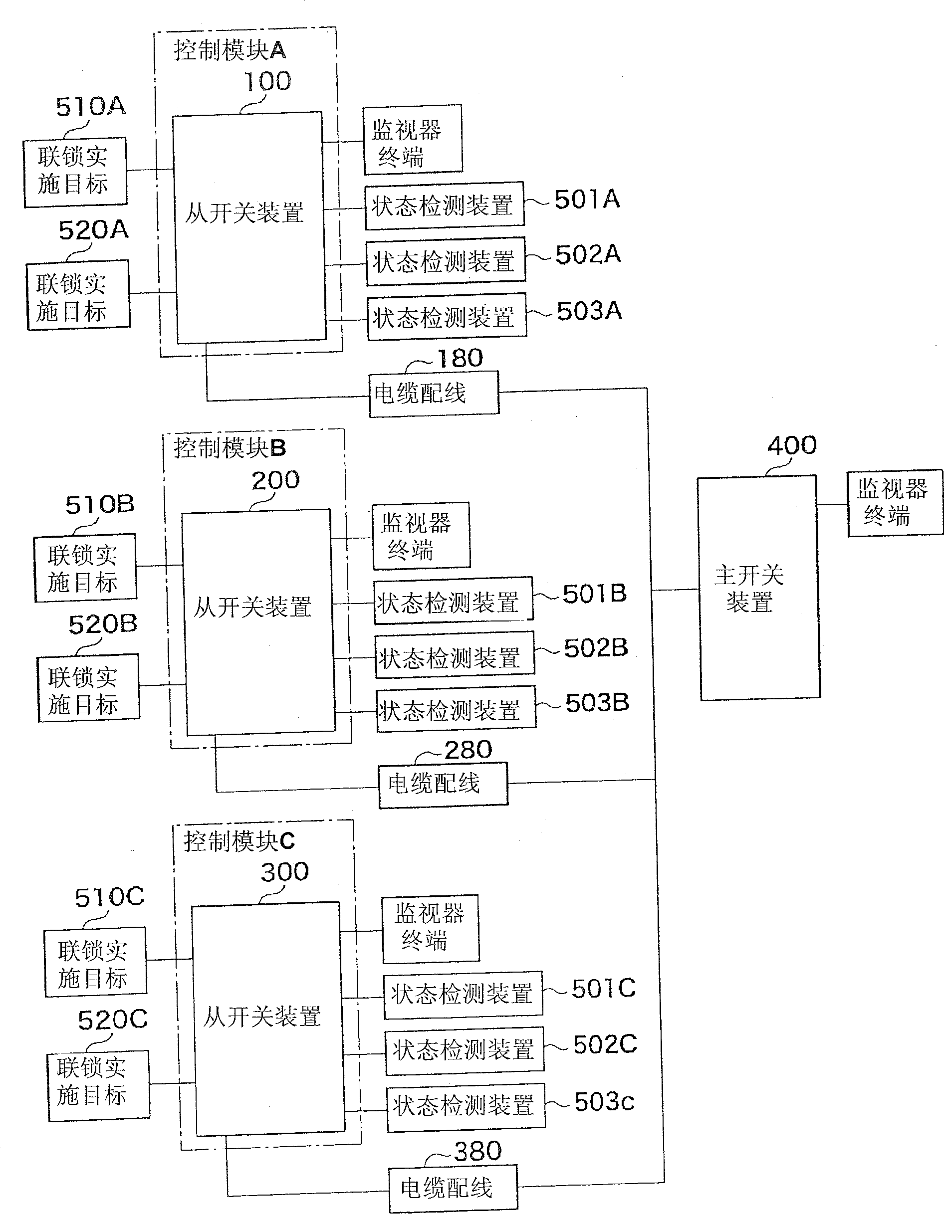
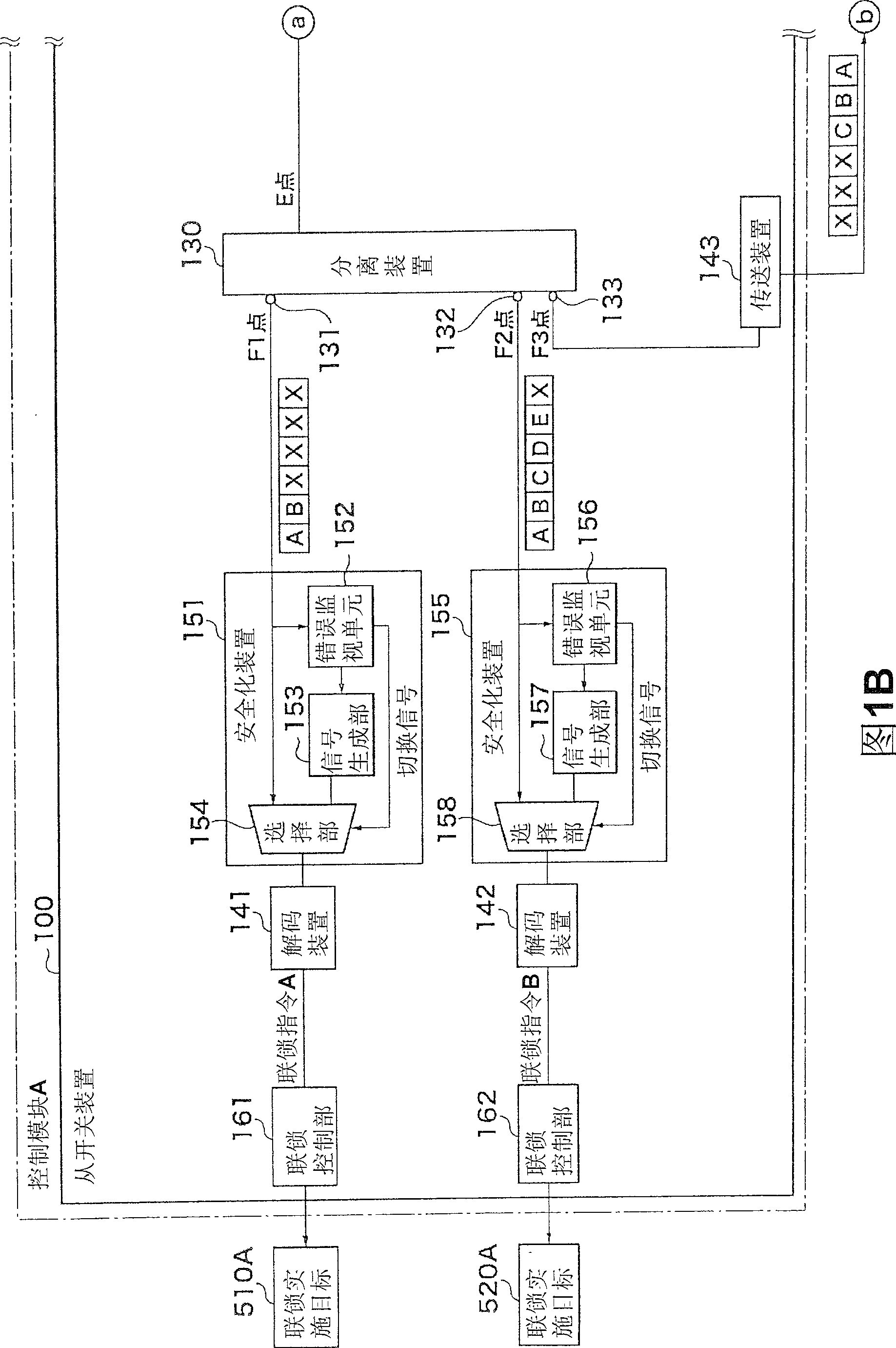
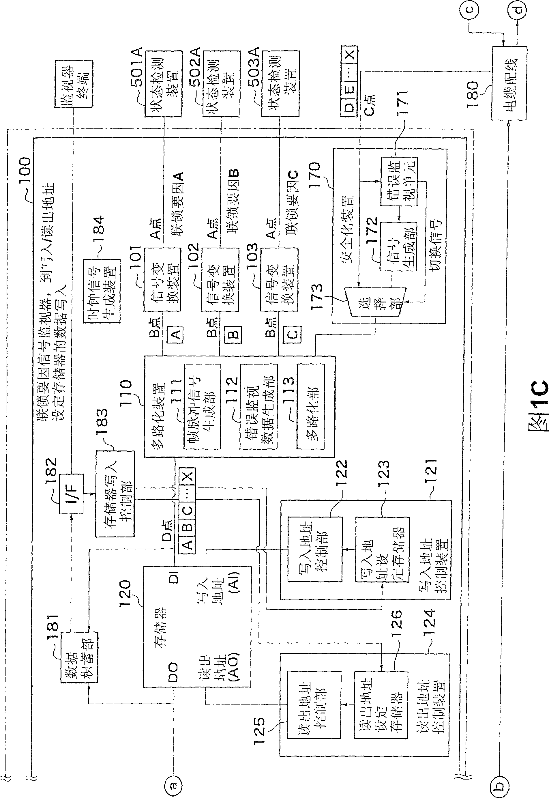
[0100] Figure 1A ~I is a block diagram showing a schematic configuration of an interlock control device according to an embodiment of the present invention, Figure 1A 1B to 1 are partial enlarged views showing the schematic configuration of the interlock control device. In the following description, the interlock control device performs interlock control among the control modules A, B, and C that control each device group in each function in the processing device that performs a plurality of processes.

[0101] like Figure 1A As shown, the interlock control device 1 has slave switching devices 100 , 200 , and 300 corresponding to control modules A, B, and C, respectively, and a master switching device 400 connecte...


PUM


Abstract

The present invention provides an interlock control apparatus which can simplify structure. The interlock control apparatus comprises slave switching apparatuses (100,200,300) corresponding respectively to the control modules and connected main switching apparatus (400). The main switching apparatuse (400) comprises a multiplexing apparatus (110) that produces a multiplexed signal for multiplexing state detecting signals by the preestablished order. A storage apparatus (120) establishes data storing multiplexed signal according to writting address. Moreover, a reading apparatus reads out the stored multiplexed signal. A separating apparatus (130) multiplexes the distributed signal by separating the read out multiplexed signal from the storage apparatus (120) and distributing to each output object so as to produce a separated signal corresponding to each output object.

Description

technical field [0001] The present invention relates to an interlock control device for a plurality of control modules, and more particularly to an interlock control device for performing interlock control among a plurality of control modules that individually drive and control at least one device in a semiconductor manufacturing device such as an etching device. Background technique [0002] In semiconductor manufacturing equipment such as conventional etching equipment, there is an interlock control function. In a semiconductor manufacturing apparatus having such a conventional interlock control function, an interlock circuit is provided in each control module for controlling a plurality of devices for realizing each function of the semiconductor manufacturing apparatus, and each control module is provided with an interlock circuit. Interlock control in one. [0003] In addition, interlock control may be performed in conjunction with each control module, and in this case,...

Claims


Application Information

Patent Timeline
Patent Type & Authority Patents(China)
IPC IPC(8): G05B9/02G05B19/04H01L21/00
Inventor 樱井敏雄
Owner TOKYO ELECTRON LTD
Why Eureka
Try Eureka