Diaphragm air pressure tank and processing technology thereof

A processing technology and air pressure tank technology, applied in the direction of climate change adaptation, climate sustainability, water saving, etc., can solve the problems of air leakage, water leakage, and the need to improve the sealing performance of the flange flange cover and the flange flange, etc. Achieve long service life, good air tightness and water tightness

Active Publication Date: 2020-08-07
上海南汇压力容器厂有限公司
View PDF5 Cites 4 Cited by
  • Summary
  • Abstract
  • Description
  • Claims
  • Application Information

AI Technical Summary

Problems solved by technology

[0004] The above-mentioned existing design scheme has the following defects. The flange flange cover and the flange flange are connected by bolts, and the contact surfaces of the flange flange cover and the flange flange are both flat

Method used


Image

  • Diaphragm air pressure tank and processing technology thereof
  • Diaphragm air pressure tank and processing technology thereof
  • Diaphragm air pressure tank and processing technology thereof

Examples


Embodiment 1

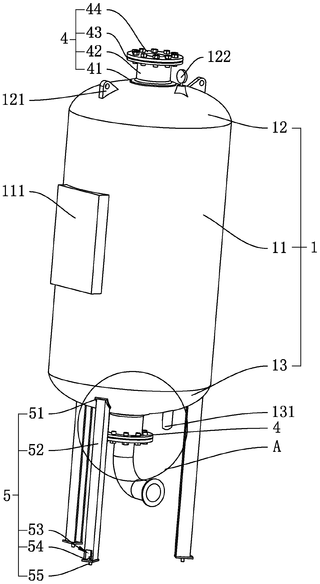
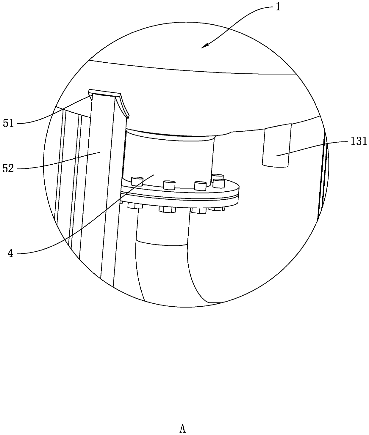
[0048] Example 1: Combining figure 1 and Figure 4 , is a diaphragm pressure tank disclosed by the present invention, comprising a steel gas tank body 1 and a rubber air bag 6, the volume of the rubber air bag 6 is smaller than that of the steel gas tank body 1, the rubber air bag 6 is located inside the steel gas tank body 1, and the steel gas tank body 1 A pressure chamber 7 is formed between the tank body 1 and the rubber airbag 6, and an inert gas is passed through the pressure chamber 7, and a water storage chamber 8 is formed inside the rubber airbag 6, and the steel gas tank body 1 is fixedly connected with bolts for fixing the rubber airbag 6. The fixed structure 4 is welded with several supporting structures 5 for supporting the steel gas tank body 1 at the bottom end of the steel gas tank body 1 .

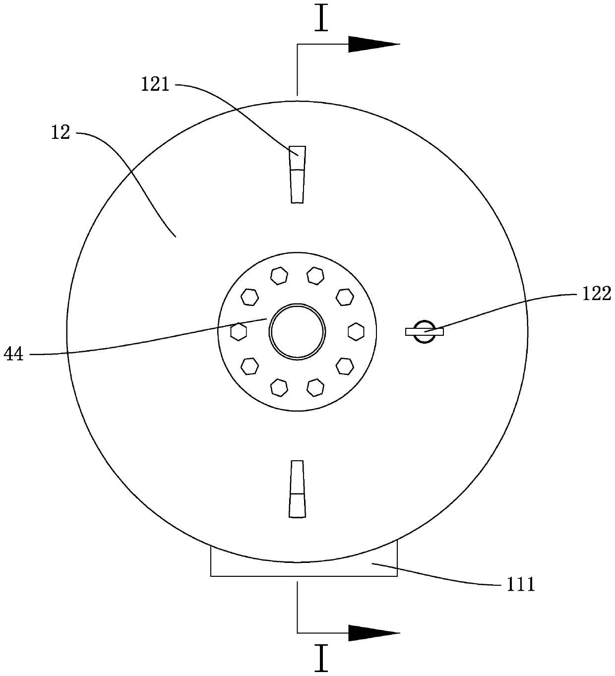
[0049] combine figure 1The steel gas tank body 1 comprises a tank body 11, an upper top cover 12 welded on the top of the tank body 11 and a lower bottom cover 13 welde...

Embodiment 2

[0059] Embodiment two: a kind of processing technique of diaphragm pressure tank, is used for producing embodiment one, and technological method comprises the following steps:

[0060] S1. Stamping two circular steel plates respectively to form an upper top cover 12 and a lower bottom cover 13;

[0061] S2. Bending the rectangular steel plate, and welding the edges in the length direction to form the tank body 11;

[0062] S3. welding the upper top cover 12 to the top of the tank body 11, and welding the lower bottom cover 13 to the bottom end of the tank body 11;

[0063] S4. Open round holes on the upper top cover 12 and the lower bottom cover 13 respectively, and weld the backing plate 41 at the round holes, weld the round pipe 42 on the backing plate 41, and weld the flange on the round pipe 42 43. Finally, the flange cover 44 is fixed on the flange plate 43 by bolts;

[0064] S5. Weld the support structure 5 on the lower bottom cover 13, install the upper air intake pip...


PUM


Abstract

The invention relates to the technical field of manufacturing and production of pressure containers, in particular to a diaphragm air pressure tank and a processing technology thereof. The diaphragm air pressure tank comprises a steel air tank body and a rubber air bag; the rubber air bag is located inside the steel air tank body, a pressure chamber is formed between the steel air tank body and the rubber air bag, a water storage chamber is formed by the rubber air bag, a fixing structure for fixing the rubber air bag is arranged on the steel air tank body, the fixing structure comprises a flange plate and a flange cover, the rubber air bag is located between the flange plate and the flange cover, a sealing structure for sealing a gap between the fixing structure and the rubber air bag isarranged in the fixing structure, the sealing structure comprises an air sealing layer used for sealing a gap of the pressure chamber at the fixing structure and a water sealing layer used for sealinga gap of the water storage chamber at the fixing structure, and the water sealing layer is fixedly connected between the rubber air bag and the flange cover. The diaphragm air pressure tank and the processing technology thereof have the effect of being good in sealing performance.

Description

technical field [0001] The invention relates to the technical field of pressure vessel production, in particular to a diaphragm pressure tank and its processing technology. Background technique [0002] Air pressure tanks are widely used in central air conditioners, boilers, water heaters, frequency conversion, and constant pressure water supply equipment. The automatic expansion and contraction of the airbag will have a certain buffering effect on the change of the water pressure, which can ensure the stability of the water pressure of the system, and the water pump will not be opened frequently due to the change of the pressure. [0003] In the prior art, a Chinese patent document with the authorized announcement number CN205530473U records a new type of vertical diaphragm pressure tank, which is composed of a steel shell and a highly elastic natural rubber air bag. The steel shell is supported by a support , flange flange cover, fastening bolt, flange flange, backing pla...

Claims


Application Information

Patent Timeline
IPC IPC(8): E03B11/06E03B11/08B23P15/00
CPCB23P15/00E03B11/06E03B11/08Y02A20/00
Inventor 朱龙明
Owner 上海南汇压力容器厂有限公司
Why Eureka
Try Eureka