Municipal parterre fence

A flower garden and municipal technology, applied in the municipal field, can solve the problems of flower damage, difficult long-term monitoring, etc., and achieve the effect of easy identification and treatment

Inactive Publication Date: 2020-08-07
刘传兵
View PDF0 Cites 0 Cited by
  • Summary
  • Abstract
  • Description
  • Claims
  • Application Information

AI Technical Summary

Problems solved by technology

[0003] In order to solve the above-mentioned technical problems, the present invention provides a municipal flower garden fence to solve the problem that existing municipal flower gardens cover a wide range of overall coverage, and it is difficult to carry out long-term monitoring, and a small amount of flowers cannot be protected after removal. The problem of a clearly identifiable differential impact as a whole, where flowers in that area have already caused more serious damage when clearly identifiable

Method used


Image

  • Municipal parterre fence
  • Municipal parterre fence
  • Municipal parterre fence

Examples


Embodiment 1

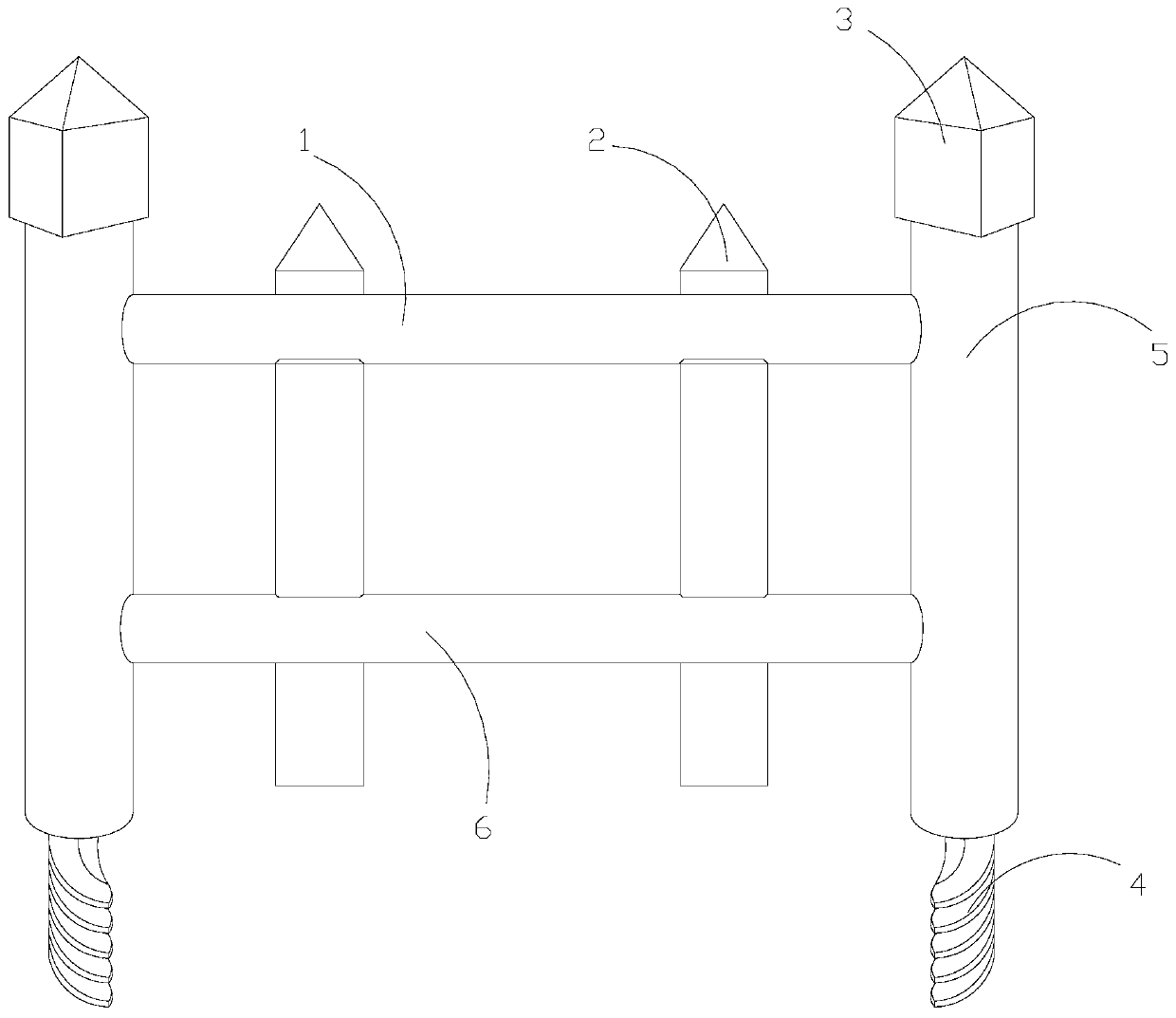
[0028] as attached figure 1 to attach Figure 6 Shown:

[0029] The invention provides a fence for a municipal garden, the structure of which includes an upper guide rail 1, a railing 2, a screw handle 3, a screw-in handle 4, a side support rod 5, and a protection control device 6, and the rail 2 runs through the Inside the upper guide bar 1, the upper guide bar 1 is embedded on the side of the side brace 5, the screw handle 3 is installed inside the side brace 5 by embedding, and the screw handle 3 is screwed into the The handles 4 are fixedly connected together, and the rails 2 are installed inside the protection regulating device 6 in an embedded manner.

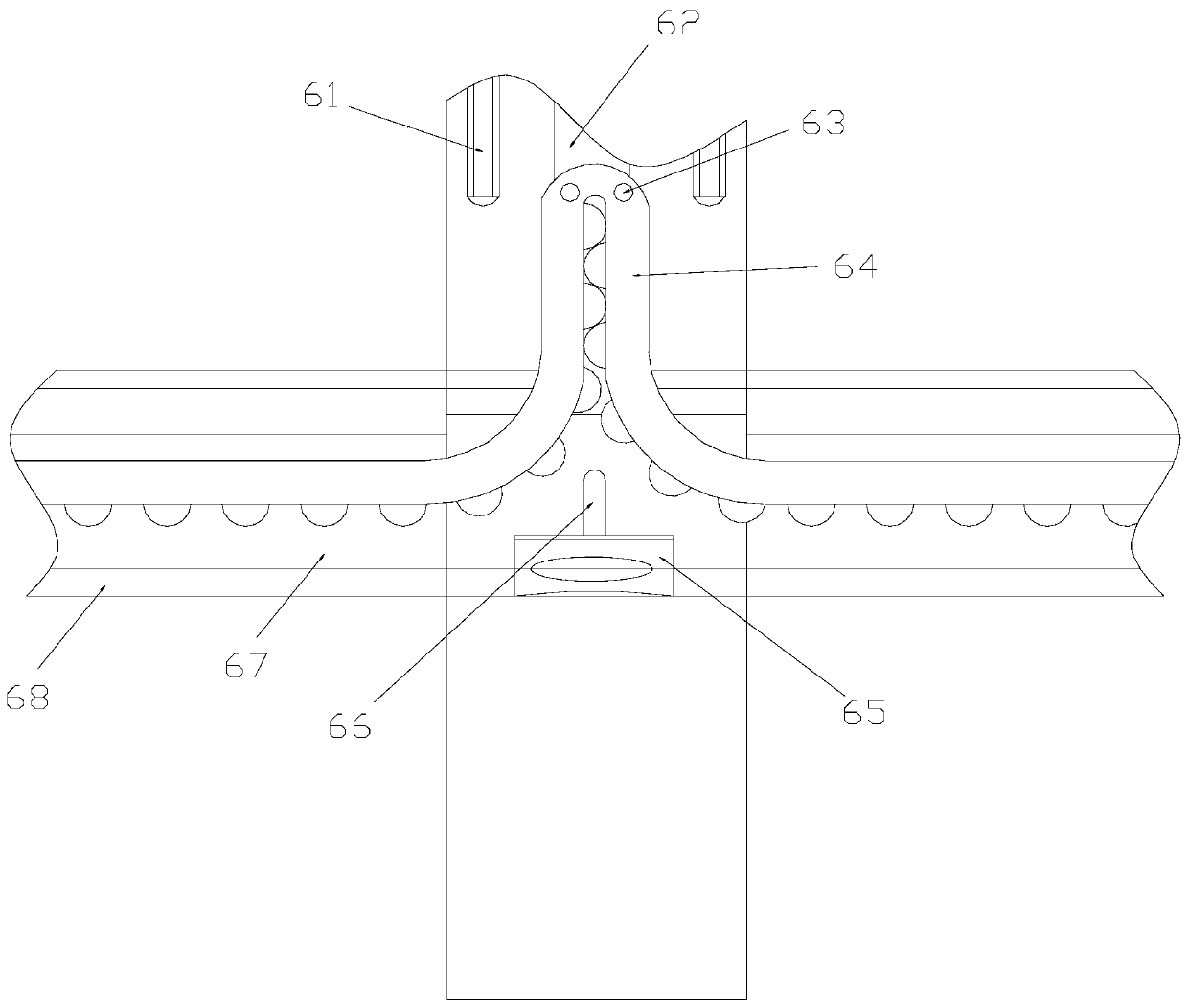
[0030] Described protective regulating device 6 comprises guide groove 61, connecting bar 62, pin rod 63, lifting connection mechanism 64, buckle piece 65, double pull wire 66, inner lock mechanism 67, cross bar cover 68, described guide groove 61 and railing 2 is an integrated structure, the connecting bar 62 is fixe...

Embodiment 2

[0037] as attached Figure 7 to attach Figure 8 Shown:

[0038] The present invention provides a municipal garden fence. The oblique pressing mechanism 675 includes an oblique stay 51, a pressing mechanism 52, and a locking block 53. A pressing mechanism 52 is provided inside the oblique stay 51. The locking block 53 is fixedly connected with the pressing mechanism 52 , and the oblique stay 51 can move upwards to generate a reset pushing force on the locking rack 671 in the inner locking mechanism 67 .

[0039] Wherein, the pressing mechanism 52 includes an arc bar a1, a connection plate a2, and an inner pressure bar a3, the arc bar a1 penetrates through the connection plate a2 laterally, and the inner pressure bar a3 is arranged inside the connection plate a2 and is connected with it. The integrated structure, the inner pressure bar a3 is attached to the arc bar a1, and the arc bar a1 will move up synchronously with the upward movement of the oblique pressing mechanism 675...


PUM


Abstract

The invention provides a municipal parterre fence. The municipal parterre fence structurally comprises an upper guide cross bar, fence bars, rotary connection handles, screw-in stems, side supportingbars and a protection regulation and control device. The upper portion of the fence bars penetrate into the upper guide cross bar. The left and right sides of the upper guide cross bar are embedded into the side faces of the side supporting bars. The rotary connection handles are mounted in the side supporting bars in an embedded mode. The rotary connection handles are fixedly connected with the screw-in stems. The fence bars are mounted in the protection regulation and control device in an embedded mode. When the municipal parterre fence bears pressure, an internal locking mechanism is passively pressed and actively releases a lifting connection mechanism, and vertical and fixed extension force-bearing points are formed through combination in the continuous embedment process of the lifting connection mechanism so that one fence bar can stably rise and is obviously separated from the other fence bars in an initial state. Thus, the municipal parterre fence can give a warning to a pickerin time and can facilitate recognition process by supervisory personnel.

Description

technical field [0001] The invention belongs to the municipal field, and more specifically relates to a municipal garden fence. Background technique [0002] In municipal construction, in order to enhance and improve the urban ecology, a certain degree of greening is required, and a certain degree of protection of the greening area is required for greening. Since municipal flower gardens often enter the flower garden to pick flowers inside the flower garden, However, because the construction of municipal flower gardens covers a wide range of overall coverage, it is difficult to conduct long-term monitoring, and a small number of flowers cannot cause obvious and identifiable differential effects on the whole after removal. The flowers in this area have already caused serious damage. Contents of the invention [0003] In order to solve the above-mentioned technical problems, the present invention provides a municipal flower garden fence to solve the problem that existing mu...

Claims


Application Information

Patent Timeline
IPC IPC(8): E04H17/14E04H17/22E04H17/00
CPCE04H17/003E04H17/1417E04H17/22
Inventor 刘传兵
Owner 刘传兵
Why Eureka
Try Eureka