Full-automatic double-motor intelligent lock

A fully automatic, dual-electric technology, applied to electric alarm locks, non-mechanical transmission-operated locks, building locks, etc., can solve problems such as motor stalling, high power consumption, and time-consuming and laborious installation of the entire lock.

Active Publication Date: 2020-08-07
佛山市耐得安智能科技有限公司
View PDF4 Cites 0 Cited by
  • Summary
  • Abstract
  • Description
  • Claims
  • Application Information

AI Technical Summary

Problems solved by technology

[0002] At present, most of the lock bodies of fully automatic smart locks in the market are mechanical lock bodies, and most of the driving mechanism components are set on the lock panel, coupled with the manual wheel for emergency unlocking, resulting in complex panel structure, time-consuming and labor-intensive installation of the entire lock, and easy There is an artificial installation failure, most of the automatic locks must be rotated after a certain period of delay after unlocking to make the oblique tongue protrude, which will double the power consumption of the motor for opening the lock once and starting twice, and even cause the motor to stall Now, because the use of a mechanical lock body must overcome the strong resistance brought by the torsion spring in the lock body, the power requirements for the motor are relatively high, and the power consumption remains high, which shortens the battery life significantly and increases the cost. Experience decline

Method used


Image

  • Full-automatic double-motor intelligent lock
  • Full-automatic double-motor intelligent lock
  • Full-automatic double-motor intelligent lock

Examples


no. 1 example

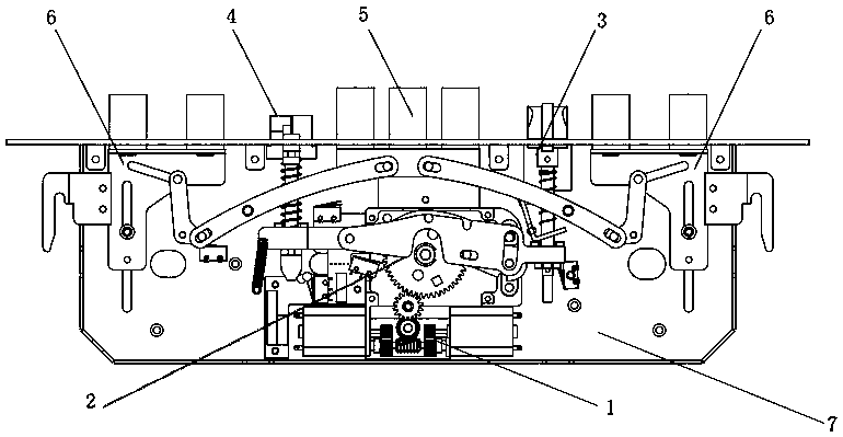
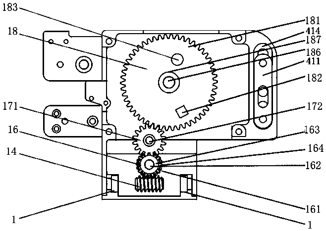
[0131] The first embodiment: a more specific unlocking process: as Figure 1-8 As shown, when unlocking, the output wheel protrusion 182 on the output gear 181 starts to rotate from the direction of 12 o'clock of the clock. At this time, the output gear 181 only drives the main tongue and the auxiliary tongue to run, and the output wheel protrusion 182 has not yet been connected with the oblique tongue. When the output wheel bump 182 turns to the direction of 2 o'clock, it hits and pushes the latch tongue transmission sheet 31 and pushes the latch bolt transmission sheet 31 to rotate counterclockwise around the latch tongue transmission sheet positioning column 312, and the output wheel When the projection 182 turns to the 4 o'clock direction, the oblique tongue driving piece 31 breaks away from the output wheel projection 182 . When the bolt driving piece 31 is pushed by the output wheel bump 182 to rotate counterclockwise, the bolt driving piece 32 is moved around the trigge...

no. 2 example

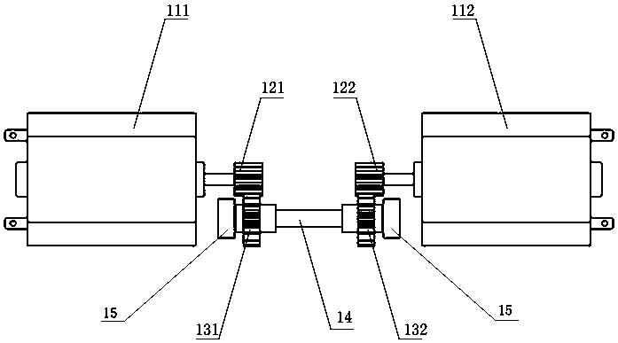
[0132] The second embodiment: a more specific locking process: such as Figure 1-8 As shown, when the door is closed and locked, the output wheel projection 182 can turn from the 6 o'clock direction to the 12 o'clock direction and stop. When locking, the driving mechanism 1 meshes with the reduction mechanism 2, and during the process of the output wheel bump 182 rotating from 6 o'clock to 12 o'clock, the output wheel main shaft 186 is linked with the main tongue rocker wheel 51 to rotate, and the rocker arm column 52 is driven by the output wheel main shaft. 186 is the center of the rocker arm turning circle, and the main tongue rocker wheel 51 is clockwise and single-direction continuous circular rotation. From 180 degrees to 360 degrees, the main tongue riveting plate 53 and the main tongue 55 will be pushed to extend; One end of the paddle arm 61 of the auxiliary tongue transmission mechanism 6 is sleeved on the paddle arm pushing column 56 of the main tongue pushing mecha...

no. 3 example

[0133] The third embodiment: a more specific trigger lock process: such as Figure 5 and Figure 6 When the trigger tongue mechanism 4 shown is in the unlocked state and the door is not pushed open, the trigger tongue 432 is retracted by the pressure of the door frame. Because the side slats of the door frame have no openings relative to the trigger tongue, the trigger tongue telescopic assembly 431 pushes the trigger block 434 away from the trigger. The toggle piece 421, the trigger toggle piece 421 is under the pulling force of the tension spring 424 and the passive column groove 423 end of the trigger toggle piece 421 is lifted to a certain angle around the trigger toggle piece positioning column (425) under the tension of the tension spring 424, so that The passive column 412 inserted in the passive column slot 423 goes up for a certain length, and the triggering drive bar 411 is guided by the positioning groove 414, and the triggering column 413 at the other end will go u...


PUM


Abstract

The invention discloses a full-automatic double-motor intelligent lock and relates to the technical field of security and anti-theft intelligent locks. The full-automatic double-motor intelligent lockcomprises a driving mechanism, an oblique tongue transmission mechanism, a main tongue pushing mechanism, an auxiliary tongue transmission mechanism, controllers, sensors, a lock body upper shell, aspeed reducing mechanism and a trigger tongue mechanism, wherein the driving mechanism, the oblique tongue transmission mechanism, the main tongue pushing mechanism, the auxiliary tongue transmissionmechanism, the controllers, the sensors, the lock body upper shell, the speed reducing mechanism and the trigger tongue mechanism are arranged on a lock body lower shell; the speed reducing mechanismis meshed with the driving mechanism and used for reducing the rotating speed of the driving mechanism and improving output torque; the speed reducing mechanism shifts the oblique tongue transmissionmechanism to make an oblique tongue do telescopic action; the speed reducing mechanism sleeves the main tongue pushing mechanism and drives a main tongue to do telescopic action; the main tongue pushing mechanism is connected with the auxiliary tongue transmission mechanism through blade arms to make an auxiliary tongue do telescopic action; and the trigger tongue mechanism triggers the oblique tongue transmission mechanism and is capable of controlling a locking oblique tongue not to pop out after retracting. According to the full-automatic double-motor intelligent lock in the invention, thelocking oblique tongue transmission mechanism can be controlled not to stretch out via the trigger tongue mechanism; even unlocking is delayed, secondary reverse rotation of the motors is not caused;and the two sets of controllers control the two sets of motors and the two sets of sensors to be mutually standby when the two sets of motors and the two sets of sensors have faults.

Description

technical field [0001] The invention relates to the technical field of security and anti-theft intelligent locks, in particular to a fully automatic double-motor intelligent lock. Background technique [0002] At present, most of the lock bodies of fully automatic smart locks in the market are mechanical lock bodies, and most of the driving mechanism components are set on the lock panel, coupled with the manual wheel for emergency unlocking, resulting in complex panel structure, time-consuming and labor-intensive installation of the entire lock, and easy There is an artificial installation failure, most of the automatic locks must be rotated after a certain period of delay after unlocking to make the oblique tongue protrude, which will double the power consumption of the motor for opening the lock once and starting twice, and even cause the motor to stall Now, because the use of a mechanical lock body must overcome the strong resistance brought by the torsion spring in the l...

Claims


Application Information

Patent Timeline
IPC IPC(8): E05B47/00E05B45/06E05B15/10E05B15/00
CPCE05B15/00E05B15/10E05B45/06E05B47/0012E05B2047/0013E05B2047/002
Inventor 蔡振巧
Owner 佛山市耐得安智能科技有限公司
Why Eureka
Try Eureka