Fully automatic dual motor smart lock
A fully automatic, dual-electric technology, applied in electric alarm locks, non-mechanical transmission-operated locks, building locks, etc., can solve the problems of time-consuming and laborious installation of the entire lock, high motor power requirements, and rising costs.
- Summary
- Abstract
- Description
- Claims
- Application Information
AI Technical Summary
Problems solved by technology
Method used
Image
Examples
no. 1 example
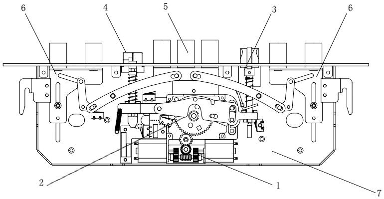
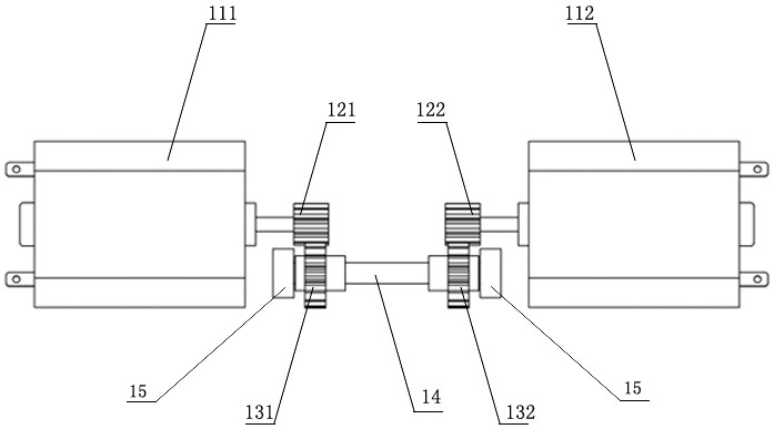
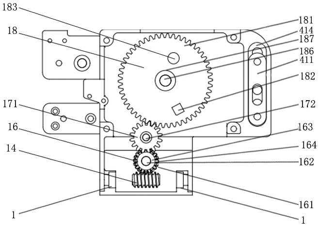
[0131] The first embodiment: a more specific unlocking process: as Figure 1-8 As shown, when unlocking, the output wheel protrusion 182 on the output gear 181 starts to rotate from the direction of 12 o'clock of the clock. At this time, the output gear 181 only drives the main tongue and the auxiliary tongue to run, and the output wheel protrusion 182 has not yet been connected with the oblique tongue. When the output wheel bump 182 turns to the direction of 2 o'clock, it hits and pushes the latch tongue transmission sheet 31 and pushes the latch bolt transmission sheet 31 to rotate counterclockwise around the latch tongue transmission sheet positioning column 312, and the output wheel When the projection 182 turns to the 4 o'clock direction, the oblique tongue driving piece 31 breaks away from the output wheel projection 182 . When the bolt driving piece 31 is pushed by the output wheel bump 182 to rotate counterclockwise, the bolt driving piece 32 is moved around the trigge...
no. 2 example
[0132] The second embodiment: a more specific locking process: such as Figure 1-8 As shown, when the door is closed and locked, the output wheel projection 182 can turn from the 6 o'clock direction to the 12 o'clock direction and stop. When locking, the driving mechanism 1 meshes with the reduction mechanism 2, and during the process of the output wheel bump 182 rotating from 6 o'clock to 12 o'clock, the output wheel main shaft 186 is linked with the main tongue rocker wheel 51 to rotate, and the rocker arm column 52 is driven by the output wheel main shaft. 186 is the center of the rocker arm turning circle, and the main tongue rocker wheel 51 is clockwise and single-direction continuous circular rotation. From 180 degrees to 360 degrees, the main tongue riveting plate 53 and the main tongue 55 will be pushed to extend; One end of the paddle arm 61 of the auxiliary tongue transmission mechanism 6 is sleeved on the paddle arm pushing column 56 of the main tongue pushing mecha...
no. 3 example
[0133] The third embodiment: a more specific trigger lock process: such as Figure 5 and Figure 6 When the trigger tongue mechanism 4 shown is in the unlocked state and the door is not pushed open, the trigger tongue 432 is retracted by the pressure of the door frame. Because the side slats of the door frame have no openings relative to the trigger tongue, the trigger tongue telescopic assembly 431 pushes the trigger block 434 away from the trigger. The toggle piece 421, the trigger toggle piece 421 is under the pulling force of the tension spring 424 and the passive column groove 423 end of the trigger toggle piece 421 is lifted to a certain angle around the trigger toggle piece positioning column (425) under the tension of the tension spring 424, so that The passive column 412 inserted in the passive column slot 423 goes up for a certain length, and the triggering drive bar 411 is guided by the positioning groove 414, and the triggering column 413 at the other end will go u...
PUM
 Abstract
Description
Claims
Application Information
 - R&D
- Intellectual Property
- Life Sciences
- Materials
- Tech Scout
- Unparalleled Data Quality
- Higher Quality Content
- 60% Fewer Hallucinations
Browse by: Latest US Patents, China's latest patents, Technical Efficacy Thesaurus, Application Domain, Technology Topic, Popular Technical Reports.
© 2025 PatSnap. All rights reserved.Legal|Privacy policy|Modern Slavery Act Transparency Statement|Sitemap|About US| Contact US: help@patsnap.com


