
Throttling hydraulic system of excavator

A technology for hydraulic systems and excavators, which is applied to earth movers/shovels, fluid pressure actuators, mechanical equipment, etc., and can solve problems such as high cost, high strength of the main shaft of the pump body, and large space occupied by the pump body. Achieve the effect of reducing quantity, reducing weight and cost, and saving installation space

Pending Publication Date: 2020-08-07
QUANZHOU KINHO CONSTR MACHINERY TECH
View PDF0 Cites 0 Cited by
  • Summary
  • Abstract
  • Description
  • Claims
  • Application Information

AI Technical Summary

Problems solved by technology

However, this oil supply method needs to use at least three or four oil supply pumps. The number of pumps is large, and the engine needs to have multiple power points; or it can be realized in the form of series pump bodies behind the pump body, but the pump body takes up space. Many, high cost, and have high requirements on the strength of the main shaft of the pump body

Method used


Image

  • Throttling hydraulic system of excavator
  • Throttling hydraulic system of excavator
  • Throttling hydraulic system of excavator

Examples


Embodiment Construction

[0029] In order to further explain the technical solution of the present invention, the present invention will be described in detail below through specific examples.

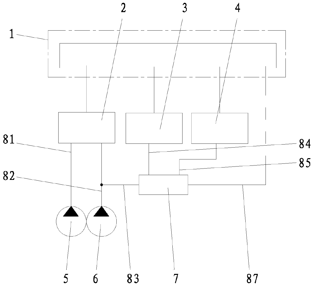
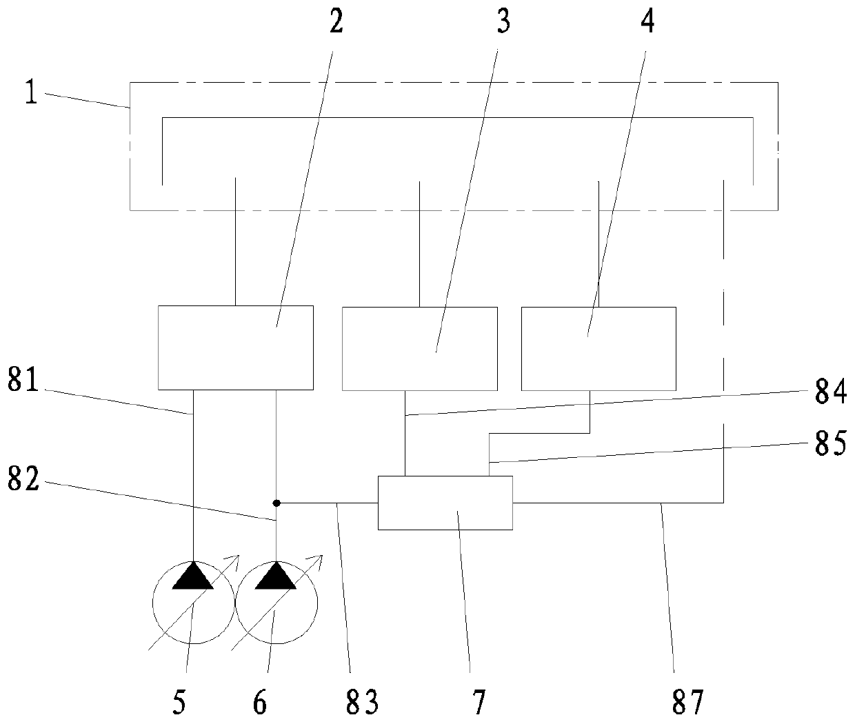
[0030] Such as Figure 2-5 As shown, an excavator throttling hydraulic system includes a hydraulic oil tank 1, and a multi-way valve 2, a steering gear 3 and a hydraulic pilot system 4 that are respectively communicated with the hydraulic oil tank 1, wherein it also includes a first pump body 5, a second The second pump body 6 and the secondary pressure reducing valve 7; the oil outlet end of the first pump body 5 has a main oil supply circuit 81 for supplying main working oil pressure to the oil inlet end of the multi-way valve 2 . The oil outlet end of the second pump body 6 has an auxiliary oil supply passage 82 for supplying oil to the oil inlet end of the multi-way valve 2, and the first oil supply passage 82 that divides the outflow part of the oil pressure from the auxiliary oil supply passage 82 to supp...


PUM


Abstract

The invention discloses a throttling hydraulic system of an excavator. The throttling hydraulic system comprises a hydraulic oil tank, a multi-way valve, a steering gear and a hydraulic pilot system,wherein the multi-way valve, the steering gear and the hydraulic pilot system communicate with the hydraulic oil tank, and further comprises a first pump body, a second pump body and a secondary pressure reducing valve, wherein the oil outlet end of the first pump body and the oil outlet end of the second pump body communicate with the oil inlet end of the multi-way valve, the oil outlet end of the second pump body further communicates with the oil inlet end of the secondary pressure reducing valve, and the oil outlet end of the secondary pressure reducing valve communicates with the oil inletend of the steering gear and the oil inlet end of the hydraulic pilot system. Compared with the prior art, the throttling hydraulic system has the beneficial effects that two pump bodies are replacedby the secondary pressure reducing valve to realize oil supply, the number of the pump bodies is reduced, and an engine only needs to provide power take-off points of the two pumps, so that the structural arrangement of the hydraulic system is facilitated, the mounting space is saved, and meanwhile, the overall weight and the cost are greatly reduced. Besides, a first pump body and a second pumpbody are adopted to supply oil to the multi-way valve and can be used for a throttling system for confluence outside the valve, selection of valve elements connected to an oil way is more flexible, and the cost of the valve elements is reduced.

Description

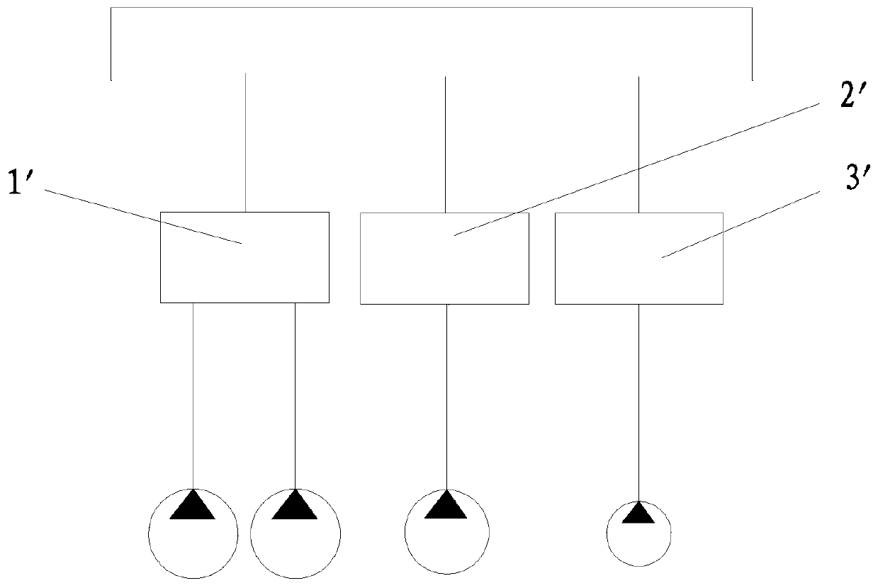
technical field [0001] The invention relates to the field of excavator hydraulic systems, in particular to an excavator throttling hydraulic system. Background technique [0002] The hydraulic system of the excavator is composed of some basic circuits and auxiliary circuits. Its function is to use oil as the working medium, use the hydraulic pump to convert the mechanical energy of the engine into hydraulic energy and transmit it, and then transfer the hydraulic energy through the hydraulic cylinder and hydraulic motor. It can be converted back into mechanical energy to realize various actions of the excavator. [0003] The hydraulic system of the existing wheeled excavator such as figure 1 As shown, it mainly includes a multi-way valve 1' for the main work, a steering gear 2' and a hydraulic pilot system 3' for manipulating the hydraulic system. When working, one or two oil supply pumps are used to provide working oil pressure to the multi-way valve 1', and another pump i...

Claims


Application Information

Patent Timeline
Patent Type & Authority Applications(China)
IPC IPC(8): F15B1/26F15B13/02F15B11/02E02F9/22
CPCE02F9/2267E02F9/2292F15B1/26F15B11/02F15B13/02F15B2211/20576
Inventor 詹小朋林文捷施正海
Owner QUANZHOU KINHO CONSTR MACHINERY TECH
Learn More