Multi-legged robot joint control method and device and multi-legged robot

A technology of a multi-legged robot and a control method, which is applied in the field of multi-legged robot joint control, and can solve problems such as high hardware requirements, complex calculation, and complex code.

Active Publication Date: 2020-08-07
UBTECH ROBOTICS CORP LTD
View PDF10 Cites 18 Cited by
  • Summary
  • Abstract
  • Description
  • Claims
  • Application Information

AI Technical Summary

Problems solved by technology

However, although the solution results using the weight matrix-based method are optimal, the calculation time for the solution is long, the code is complex, and the hardware requirements are high.
In addition, this type of method will bring two problems, that is, no matter how much the weight difference is, the low-weight component will still affect the high-weight component; secondly, for different gaits, due to the different number and position of the robot's supporting legs, often Different weights are required, so the weight matrix needs to be adjusted continuously according to different situations, resulting in more complicated calculations, etc.

Method used


Image

  • Multi-legged robot joint control method and device and multi-legged robot
  • Multi-legged robot joint control method and device and multi-legged robot
  • Multi-legged robot joint control method and device and multi-legged robot

Examples


Embodiment 1

[0059] Please refer to figure 1 , this embodiment proposes a multi-legged robot joint control method. The method mainly includes the following steps:

[0060] Step S10, obtaining the current trunk pose and trunk force of the multi-legged robot, and each joint angle of each supporting leg.

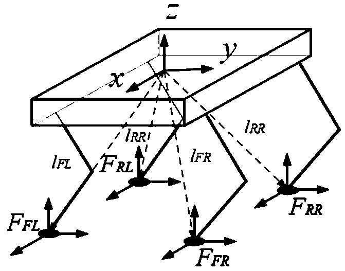
[0061] Exemplarily, the torso pose (including position and pose) of the multi-legged robot can be obtained by measuring an inertial measurement unit (IMU) or other pose sensors. The torso force can be calculated by the controller. Generally, when it is necessary to control the robot torso to reach a certain state, it is necessary to first determine the torso force required by the multi-legged robot according to the planned torso trajectory or target state. Wherein, the torso force includes the torso force in different directions. Usually, the force on the torso is a six-dimensional vector, including forces in X, Y, and Z directions and moments in X, Y, and Z directions.

[0062] For a r...

Embodiment 2

[0124] Please refer to Figure 5 , based on the method of the above-mentioned embodiment 1, this embodiment proposes a multi-legged robot joint control device 10, including:

[0125] The information acquisition module 110 is configured to acquire the current trunk posture and trunk force of the multi-legged robot, and each joint angle of each supporting leg, wherein the trunk stress includes the trunk's stress in different directions.

[0126] A mapping matrix construction module 120, configured to construct a mapping matrix from the trunk force to the expected plantar support force of all support legs according to the trunk pose, the force on the trunk and the joint angles of each supporting leg .

[0127] The target prioritization module 130 is configured to perform target prioritization on the force of the torso in different directions to obtain several priority targets, determine a weight matrix for each priority target and based on the mapping matrix and the The weight ...


PUM


Abstract

The embodiment of the invention discloses a multi-legged robot joint control method and device and a multi-legged robot. The method comprises: constructing a mapping matrix of expected foot bottom supporting force of a trunk stressed to all supporting legs; carrying out target priority division on the trunk stress, determining a weight matrix of each priority target, and constructing an optimization model of each priority target about the expected plantar supporting force based on the mapping matrix and the weight matrix; sequentially solving each optimization model to obtain a corresponding expected plantar supporting force; wherein the expected plantar supporting force corresponding to the current priority target serves as a solving basis of the expected plantar supporting force of the next priority target; calculating a joint moment of the support leg for joint control based on the plantar desired support force and the Jacobian matrix. According to the technical scheme, the big problem that in the prior art, no matter how to adjust the stress weight of the body, all components influence one another can be well solved, and for different gaits, the weight does not need to be adjusted when the gaits are changed.

Description

technical field [0001] The invention relates to the technical field of multi-legged robots, in particular to a multi-legged robot joint control method and device, and a multi-legged robot. Background technique [0002] Whether it is a quadruped robot with position-controlled joints or force-controlled joints, it is necessary to calculate the torque required by each joint of the robot. In the process of controlling the walking of the quadruped robot, the control goal is usually to make the torso of the robot reach a certain state (position and speed), and what the controller calculates is the virtual force and moment required for the torso of the robot to reach the specified state. This is a 6 dimensional vector (abbreviated as 6-dimensional force). Since the torso of the robot cannot be directly subjected to external forces other than gravity, it is necessary to map the force on the torso of the robot to the supporting force of the soles of the feet in contact with the grou...

Claims


Application Information

Patent Timeline
Patent Type & Authority Applications(China)
IPC IPC(8): G05D1/08B62D57/032
CPCG05D1/0891B62D57/032B25J9/1607B25J13/085B25J13/088
Inventor 徐喆赵明国熊友军
Owner UBTECH ROBOTICS CORP LTD
Why Eureka
Try Eureka