
Polarization and directional diagram composite reconfigurable antenna

A technology for reconstructing antennas and patterns, which is applied in the fields of antennas, wireless communications, and remote sensing and telemetry. simple structure

Inactive Publication Date: 2020-08-07
XIDIAN UNIV
View PDF11 Cites 11 Cited by
  • Summary
  • Abstract
  • Description
  • Claims
  • Application Information

AI Technical Summary

Problems solved by technology

[0006] The purpose of the present invention is to overcome the defects of the above-mentioned prior art, and propose a polarization and pattern composite reconfigurable antenna, which is used to solve the problem of the lack of reconfigurable polarization states in the prior art. There are many electrical ports, which lead to complex technical problems in the feeding system

Method used


Image

  • Polarization and directional diagram composite reconfigurable antenna
  • Polarization and directional diagram composite reconfigurable antenna
  • Polarization and directional diagram composite reconfigurable antenna

Examples


Embodiment Construction

[0034] Below in conjunction with accompanying drawing and specific embodiment, the present invention is described in further detail:

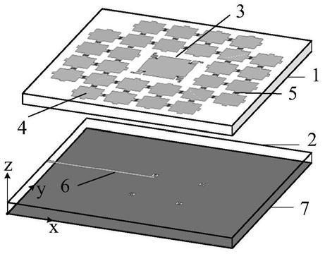
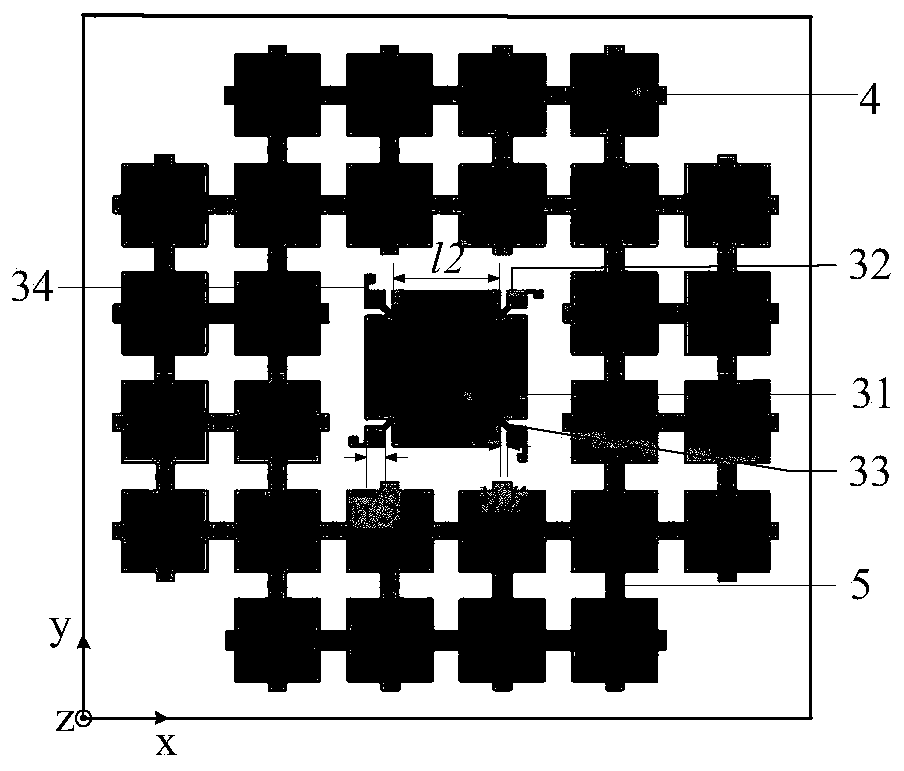
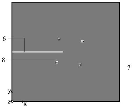
[0035] refer to figure 1 , the present invention comprises a first dielectric substrate 1 and a second dielectric substrate 2 stacked up and down, wherein the thickness of the first dielectric substrate 1 is 1 mm, and a square F4BM material with a dielectric constant of 2.65 and a loss tangent of 0.002 is used. The length is 80mm; the thickness of the second dielectric substrate 2 is 1mm, and the same material as the first dielectric substrate 1 is used, and its physical size is 80mm×86mm; considering the welding of the coaxial head in the actual measurement process, the designed second dielectric The long side of the substrate 2 is longer than the first dielectric substrate 1. As far as the coordinate system in the figure is concerned, the positive end of the second dielectric substrate 2 along the x-axis is aligned with the positive end of th...


PUM


Abstract

The invention provides a polarization and directional diagram composite reconfigurable antenna, and aims at solving the technical problem that a feed system is complex due to the fact that reconfigurable polarization states are few and the number of feed ports of an antenna unit is large. The antenna comprises a first dielectric substrate and a second dielectric substrate which are stacked up anddown. A radio frequency switch is loaded on the upper surface of the first dielectric substrate, and comprises an equivalent RF switch for connecting a cross-shaped metal patch and a rectangular patchand an ideal RF switch used for connecting different parasitic pixel patches. By controlling the on and off states of the radio frequency switches, the antenna can realize three polarization states,namely linear polarization, left-handed circular polarization and right-handed circular polarization, and in each polarization state, the reconfigurable parasitic pixel patches can deflect the main beam, so that the antenna can be applied to the fields of remote sensing and telemetering, wireless communication and the like.

Description

technical field [0001] The invention belongs to the technical field of antennas, and relates to a reconfigurable antenna combined with polarization and pattern, which can be applied to the fields of remote sensing and telemetry, wireless communication and the like. Background technique [0002] With the advancement of science and technology, people's demand for information has increased unprecedentedly, making communication technology develop by leaps and bounds. As an important branch of the communication field, wireless communication has been widely used in various fields such as national defense and people's livelihood because it gets rid of the dependence on physical transmission lines. The antenna is the information entrance and exit of radio equipment, and the performance of the antenna directly affects the communication quality of the entire wireless communication system. [0003] Nowadays, wireless communication is gradually accelerating into the multi-functional, l...

Claims


Application Information

Patent Timeline
Patent Type & Authority Applications(China)
IPC IPC(8): H01Q25/00H01Q15/24H01Q1/50
CPCH01Q1/50H01Q15/242H01Q25/00
Inventor 李文涛魏萌王一鸣蘧浩天史小卫
Owner XIDIAN UNIV
Learn More