Heat dissipation protection device for electromechanical equipment

A technology for protection devices and electromechanical equipment, which is applied to structural components of electrical equipment, electrical equipment shells/cabinets/drawers, electrical components, etc., and can solve the problems of shortening the service life of electromechanical equipment, damage to internal components of electromechanical equipment, and contact between moisture and electromechanical equipment Excessive and other problems, to avoid moisture damage, easy to operate, simple and labor-saving installation process

Active Publication Date: 2020-08-07
山东水利职业学院
View PDF13 Cites 2 Cited by
  • Summary
  • Abstract
  • Description
  • Claims
  • Application Information

AI Technical Summary

Problems solved by technology

[0004] However, when the device is loaded with electromechanical equipment, it is necessary to lift the electromechanical equipment before placing it on the slider. For large electromechanical equipment, it is extremely inconvenient to use a forklift to assist it. , The surrounding environment of the electromechanic

Method used


Image

  • Heat dissipation protection device for electromechanical equipment
  • Heat dissipation protection device for electromechanical equipment
  • Heat dissipation protection device for electromechanical equipment

Examples


Embodiment 1

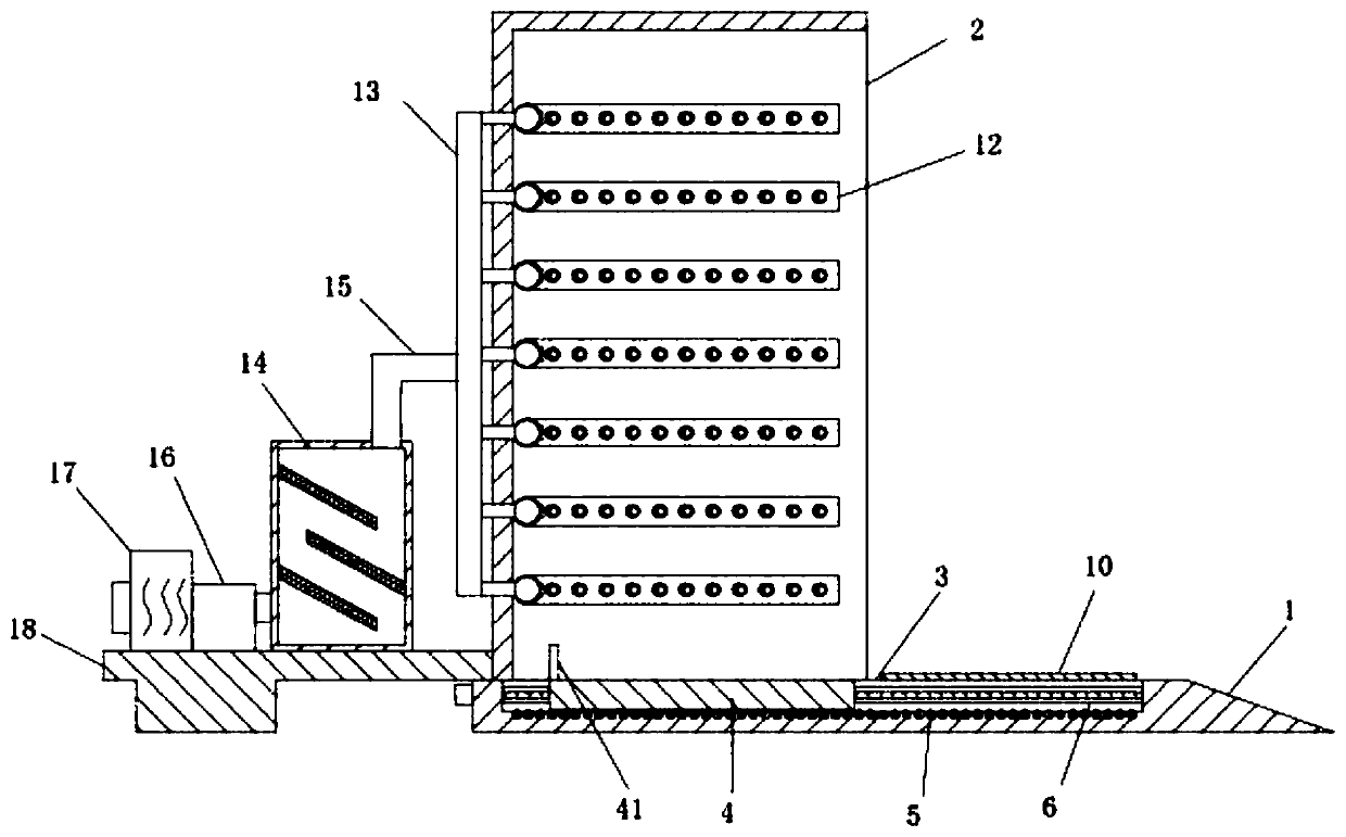
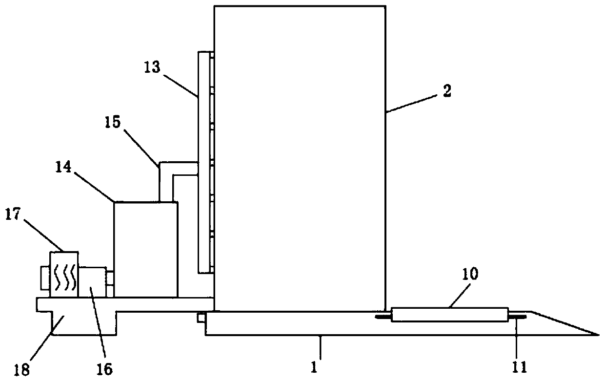
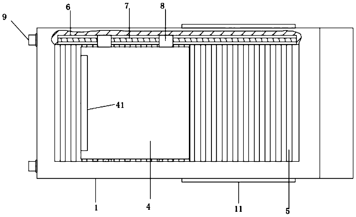
[0028] The invention provides a technical solution: a heat dissipation protection device for electromechanical equipment, including a base 1, a protective cover 2 is provided on the left side of the top of the base 1, the right side of the protective cover 2 is open, and the top of the base 1 There is a groove 3, and the inner cavity of the groove 3 is slidably provided with a support plate 4, and the groove 3 is symmetrically provided with a chute 6 front and rear, and a driving mechanism is arranged in the chute 6, and the support plate 4 and the The driving mechanism is connected, and the inner wall of the protective cover 2 is distributed with air outlet pipes 12. The air outlet pipes 12 have multiple groups, and the multiple groups of air outlet pipes 12 are distributed at equal intervals from top to bottom. On the left side wall of the protective cover 2 A standpipe 13 is provided, and the standpipe 13 communicates with all outlet pipes 12. The left end of the base 1 is p...

Embodiment 2

[0031] The bottom surface of the groove 3 is evenly distributed with rollers 5, and the bottom surface of the support plate 4 slides against the top surface of the rollers 5. This structure can greatly reduce the resistance during the load-bearing movement of the support plate 4 and reduce the energy consumption of the driving mechanism. .

Embodiment 3

[0033] Protruding rails 11 are provided on the right side of the front and rear walls of the base 1 , and cover plates 10 are slidably installed between the protruding rails 11 on both sides.

[0034] The cover plate 10 includes a U-shaped plate body 101, and the inner sides of the vertical plates on both sides of the U-shaped plate body 101 are provided with convex rail slide grooves 102;

[0035] The above structure can cover the groove 3 at the front after the electromechanical equipment moves to the protective cover 2, which is convenient for the staff to operate on the front side of the electromechanical equipment.


PUM


Abstract

The invention discloses an electromechanical equipment heat dissipation protection device, and belongs to the technical field of heat dissipation protection devices. The device comprises a base, wherein a protective cover is arranged on the left side of the top end of the base, the right side of the protective cover is open, a groove is formed in the top end of the base, a supporting plate is arranged in the inner cavity of the groove in a sliding manner, sliding grooves are formed in the groove in a front-back symmetry mode, and a driving mechanism is arranged in the sliding groove. Accordingto the invention, a groove is formed in the surface of a base, and a movable supporting plate is arranged in the groove, so that when electromechanical equipment is supported, raising operation is not required, and the mounting process of the electromechanical equipment is simple and labor-saving; by arranging a drying box, dehumidification operation can be conducted on air entering a protectivecover, so that airflow blown to the electromechanical equipment is dry, and the electromechanical equipment is prevented from being affected with damp damage; the resistance generated when the supporting plate moves in a loaded mode is reduced through the arranged roller column; and the groove can be covered through the arranged cover plate, so that personnel can stand in front of the equipment tooperate conveniently.

Description

technical field [0001] The invention relates to the technical field of heat dissipation protection devices, in particular to a heat dissipation protection device for electromechanical equipment. Background technique [0002] People have more and more demands on electromechanical equipment in their daily life. From vehicles to various household appliances, computers, printers, etc., electromechanical products have become indispensable in people's life. Advanced mechanical and electrical equipment can greatly increase labor productivity, reduce labor intensity, improve the production environment, and complete tasks that cannot be done by manpower. At present, there are few devices for cooling electromechanical equipment, and the existing devices are not obvious enough to cool electromechanical equipment, have relatively low efficiency, and are not convenient enough. [0003] Patent No. CN201920091378.5 discloses a heat dissipation protection device for electromechanical equip...

Claims


Application Information

Patent Timeline
IPC IPC(8): H05K5/02H05K7/20B01D53/26
CPCB01D53/26H05K5/0234H05K7/20145
Inventor 许殿生董科孙珊珊万云霞
Owner 山东水利职业学院
Why Eureka
Try Eureka