A crank pedal mechanism with a side warning mechanism for shared bicycles
A technology for sharing bicycles and pedals, which is applied to crank structures, vehicle parts, bicycle accessories, etc., can solve the problems of poor reflection effect of reflectors, and achieve the effect of improving warning effect, facilitating riding, and outstanding warning effect.
- Summary
- Abstract
- Description
- Claims
- Application Information
AI Technical Summary
Problems solved by technology
Method used
Image
Examples
Embodiment 1
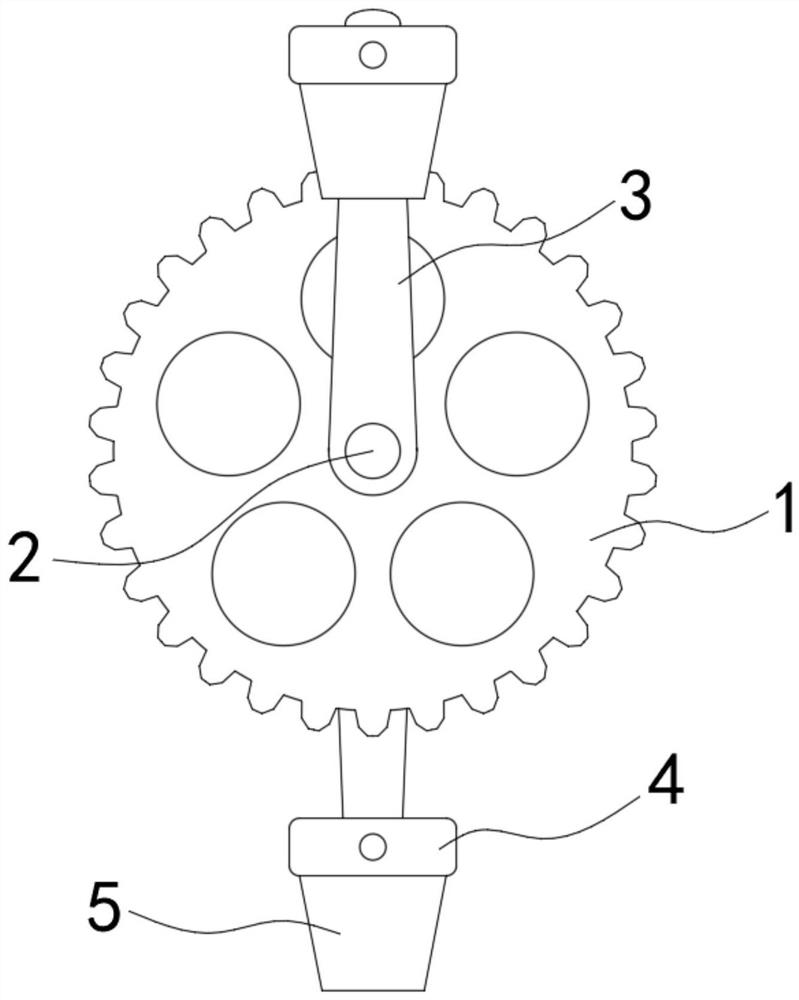
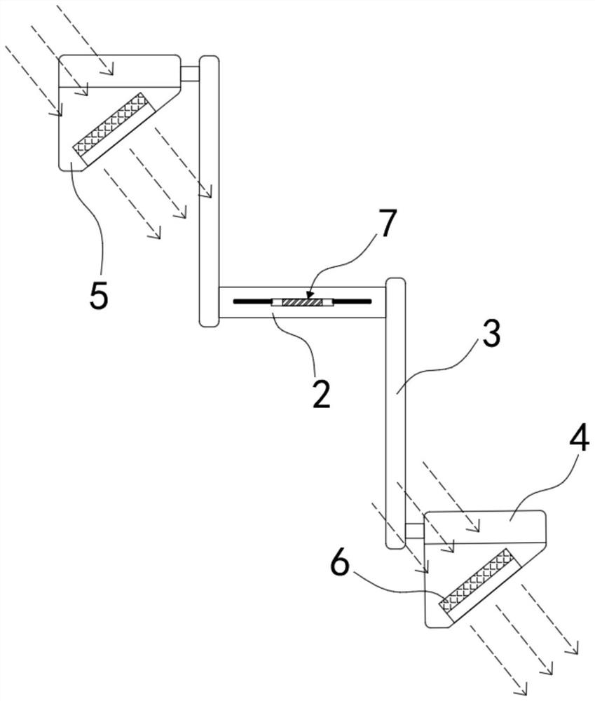
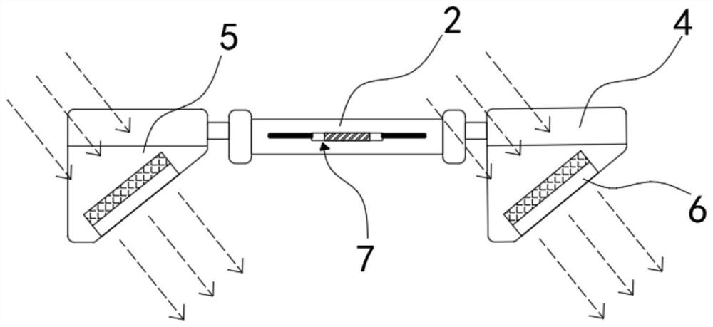
[0026] Such as Figure 1-5 As shown, a crank pedal mechanism with a side warning mechanism for a shared bicycle includes a driving disc 1, a fixed shaft 2, two sets of cranks 3 and two pedals 4, and the fixed shaft 2 is coaxially fixedly connected to the driving disc 1 Inside, the two cranks 3 are respectively fixedly installed on the two ends of the fixed shaft 2, the pedal 4 is rotated and installed on the end of the crank 3, and the lower end of the pedal 4 is fixedly connected with a wedge-shaped mounting seat 5, under the action of the mounting seat 5, The entire center of gravity of the pedal 4 and the mounting seat 5 is located on the mounting seat 5, so that the pedal 4 is always kept on the plane, which is convenient for riding. The permanent magnet block 6 is fixedly installed in the mounting seat 5, and two permanent magnet blocks The 6 magnetic poles are the same and are all inclined in the same direction. During the riding process, the positional relationship betw...
Embodiment 2
[0031] Such as Figure 6-8 As shown, the difference between this embodiment and Embodiment 1 is that: the light guide 11 includes annular light-emitting tubes 13 arranged on both sides of the fixed shaft 2, and the annular light-emitting tubes 13 communicate with the fixed shaft 2 through a plurality of light guide tubes 14 , the interior of the ring-shaped luminous tube 13, the light guide 14 and the fixed shaft 2 are all provided with a reflective layer, the ring-shaped luminous tube 13 is fixedly connected on the side wall of the driving disk 1, and the ring-shaped luminous tube 13 is located on the side wall outside the driving disk 1 A circle of transparent ring 15 is embedded.
[0032] In this embodiment, the light emitted by the LED lamp 10 is transmitted to the ring-shaped light-emitting tube 13 through the light guide tube 14, and is emitted at the transparent ring 15, as Figure 6 As shown, the transparent ring 15 can further increase the warning range and achieve a...
Embodiment 3
[0034] Such as Figure 9 As shown, the difference between this embodiment and Embodiment 1 is that: the transparent ring 15 is pasted with a colored transparent band 16, and the colored transparent band 16 includes a plurality of transparent segments of different colors, so that the light of each part of the annular light emitting tube 13 Colors vary.
[0035] In this embodiment, since the light color of each part of the ring-shaped luminous tube 13 is different, and the ring-shaped luminous tube 13 is fixed on the driving disk 1, it will rotate with the driving disk 1, therefore, the various colors emitted by the ring-shaped luminous tube 13 The light will continue to rotate and superimpose, so as to produce richer colors, which can further attract people's attention and improve the warning effect.
PUM
 Abstract
Description
Claims
Application Information
 - R&D
- Intellectual Property
- Life Sciences
- Materials
- Tech Scout
- Unparalleled Data Quality
- Higher Quality Content
- 60% Fewer Hallucinations
Browse by: Latest US Patents, China's latest patents, Technical Efficacy Thesaurus, Application Domain, Technology Topic, Popular Technical Reports.
© 2025 PatSnap. All rights reserved.Legal|Privacy policy|Modern Slavery Act Transparency Statement|Sitemap|About US| Contact US: help@patsnap.com


