Municipal environment-friendly sewage treatment device

A sewage treatment device and environmental protection technology, applied in the direction of water/sewage treatment, water/sewage multi-stage treatment, water/sludge/sewage treatment, etc., can solve the problems of inconvenient and efficient use, achieve convenient and efficient use, and avoid mixing Insufficient, better sealing effect

Inactive Publication Date: 2020-08-11
袁迎节
View PDF1 Cites 2 Cited by
  • Summary
  • Abstract
  • Description
  • Claims
  • Application Information

AI Technical Summary

Problems solved by technology

The high-efficiency municipal sewage treatment device in the above-mentioned patents has the following deficiencies: it is not convenient and efficient to use

Method used


Image

  • Municipal environment-friendly sewage treatment device
  • Municipal environment-friendly sewage treatment device
  • Municipal environment-friendly sewage treatment device

Examples


Embodiment 1

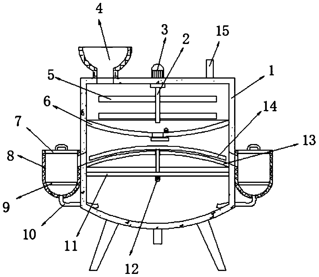
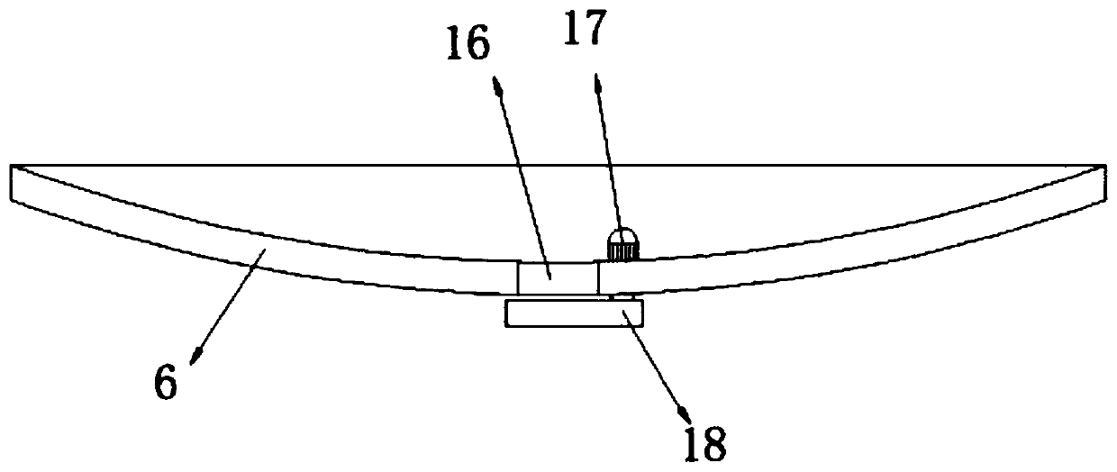
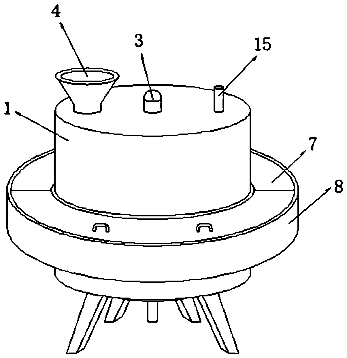
[0027] refer to Figure 1-3 , a sewage treatment device for municipal environmental protection, comprising a barrel body 1, the top outer wall of the barrel body 1 is sequentially inserted with a water inlet pipe 4 and a feeding pipe 15, and the top outer wall of the barrel body 1 is connected with a stirring motor 3 through fastening bolts , the output shaft of the stirring motor 3 is connected with the rotating rod 2 through fastening bolts, and the circumference of the rotating rod 2 is connected with the stirring paddle 5 through the fastening bolts, and the top of the inner wall of the barrel body 1 is connected with the transverse diaphragm through the fastening bolts 6. The outer wall of the bottom of the diaphragm 6 is provided with a discharge opening 16, and the bottom of the inner wall of the barrel body 1 is connected with an arc-shaped mesh plate 13 through fastening bolts, and the side of the arc-shaped mesh plate 13 close to the transverse diaphragm 6 is On the ...

Embodiment 2

[0037] refer to Figure 4 , a warp knitting machine pulling and coiling device for weaving plastic nets. Compared with Embodiment 1, the top of the sealing plate 18 in this embodiment is provided with an installation groove, and the bottom inner wall of the installation groove is connected by fastening bolts. Air bag 19, the position of air bag 19 is corresponding to the opening position of feeding port 16, and the bottom of sealing plate 18 is connected with air pump 20 by fastening bolt, and the air outlet of air pump 20 passes connecting pipe and air bag 19.

[0038] Working principle: When the sealing plate 18 is used to block the feeding port 16, the air pump 20 inflates the air bag 19, and the air bag 19 is inflated to fill and block the feeding port 16. The sealing effect is better, and part of the sewage or drug retention is avoided. Insufficient mixing at feed opening 16.


PUM


Abstract

The invention discloses a municipal environment-friendly sewage treatment device comprising a barrel body. A water inlet pipe and a feeding pipe are sequentially inserted into the outer wall of the top of the barrel body; a stirring motor is arranged on the outer wall of the top of the barrel body; a rotating rod is arranged on the output shaft of the stirring motor; a stirring paddle is arrangedat the circumference of the rotating rod, a transverse partition plate is arranged at the top of the circumferential inner wall of the barrel body, a discharging opening is formed in the outer wall ofthe bottom of the transverse partition plate, an arc-shaped net plate is arranged at the bottom of the circumferential inner wall of the barrel body, the side, close to the transverse partition plate, of the arc-shaped net plate is an outer arc surface, and a collecting groove is formed in the bottom of the circumferential outer wall of the barrel body. When the device is used, the device is used, the stirring motor drives the stirring paddle to fully mix the sewage and the medicine, the arc-shaped net plate filters the mixed sewage flowing out of the discharging opening, filtered impuritiesslide to the penetrating holes from the outer arc face of the arc-shaped net plate, the collecting groove collects the impurities sliding out of the penetrating holes, the situation that the filteringefficiency is affected due to the fact that the impurities are accumulated on the arc-shaped net plate is avoided, and use is convenient and efficient.

Description

technical field [0001] The invention relates to the technical field of municipal environmental protection, in particular to a sewage treatment device for municipal environmental protection. Background technique [0002] Sewage treatment equipment is a kind of industrial equipment that can effectively treat domestic sewage and industrial wastewater in urban areas. It prevents sewage and pollutants from flowing directly into waters, which is of great significance to improving the ecological environment, improving urban quality and promoting economic development. [0003] After retrieval, the Chinese patent publication number is CN109704482A, which discloses a high-efficiency municipal sewage treatment device, including a sedimentation tank and a purification tank. One side is provided with a water inlet, the bottom of the side of the purification tank away from the connecting pipe is provided with a drain outlet, and the inner upper part of the sedimentation tank is fixed with...

Claims


Application Information

Patent Timeline
Patent Type & Authority Applications(China)
IPC IPC(8): C02F9/04
CPCC02F1/00C02F1/001
Inventor 钟曼璇
Owner 袁迎节
Why Eureka
Try Eureka