Highway bridge roadbed and pavement construction device and construction method thereof

A technology for highway bridges and construction devices, applied to bridges, bridge parts, bridge construction, etc., to achieve the effects of improving speed and efficiency, saving manpower, and ensuring quality

Active Publication Date: 2020-08-11
李春育
View PDF10 Cites 4 Cited by
  • Summary
  • Abstract
  • Description
  • Claims
  • Application Information

AI Technical Summary

Problems solved by technology

[0004] The technical task of the present invention is to address the above deficiencies, to provide a highway bridge subgrade pavement construction device and its construction method, to solve the problem of how to better lay concrete during pavement construction

Method used


Image

  • Highway bridge roadbed and pavement construction device and construction method thereof
  • Highway bridge roadbed and pavement construction device and construction method thereof
  • Highway bridge roadbed and pavement construction device and construction method thereof

Examples


Embodiment 1

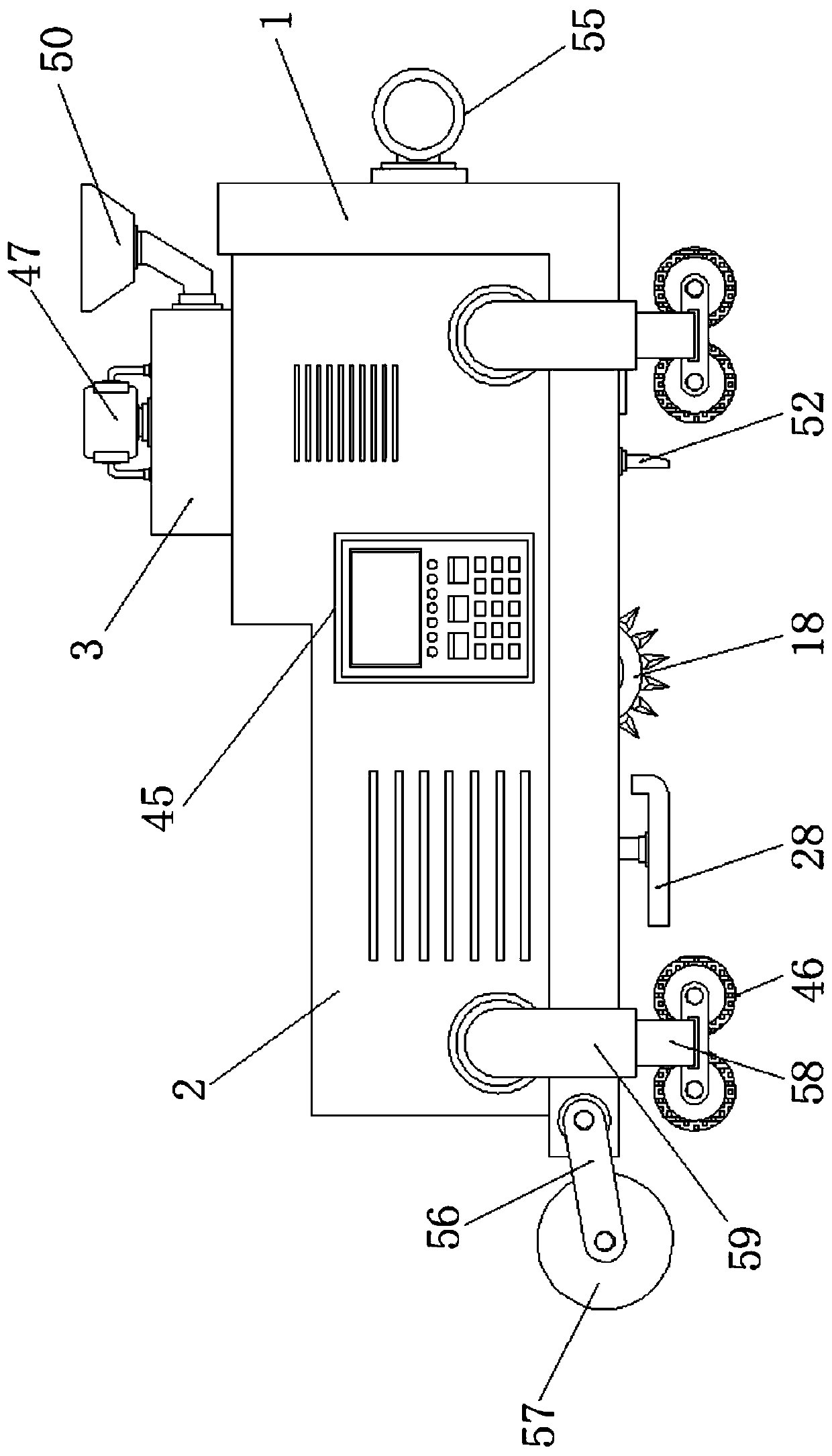
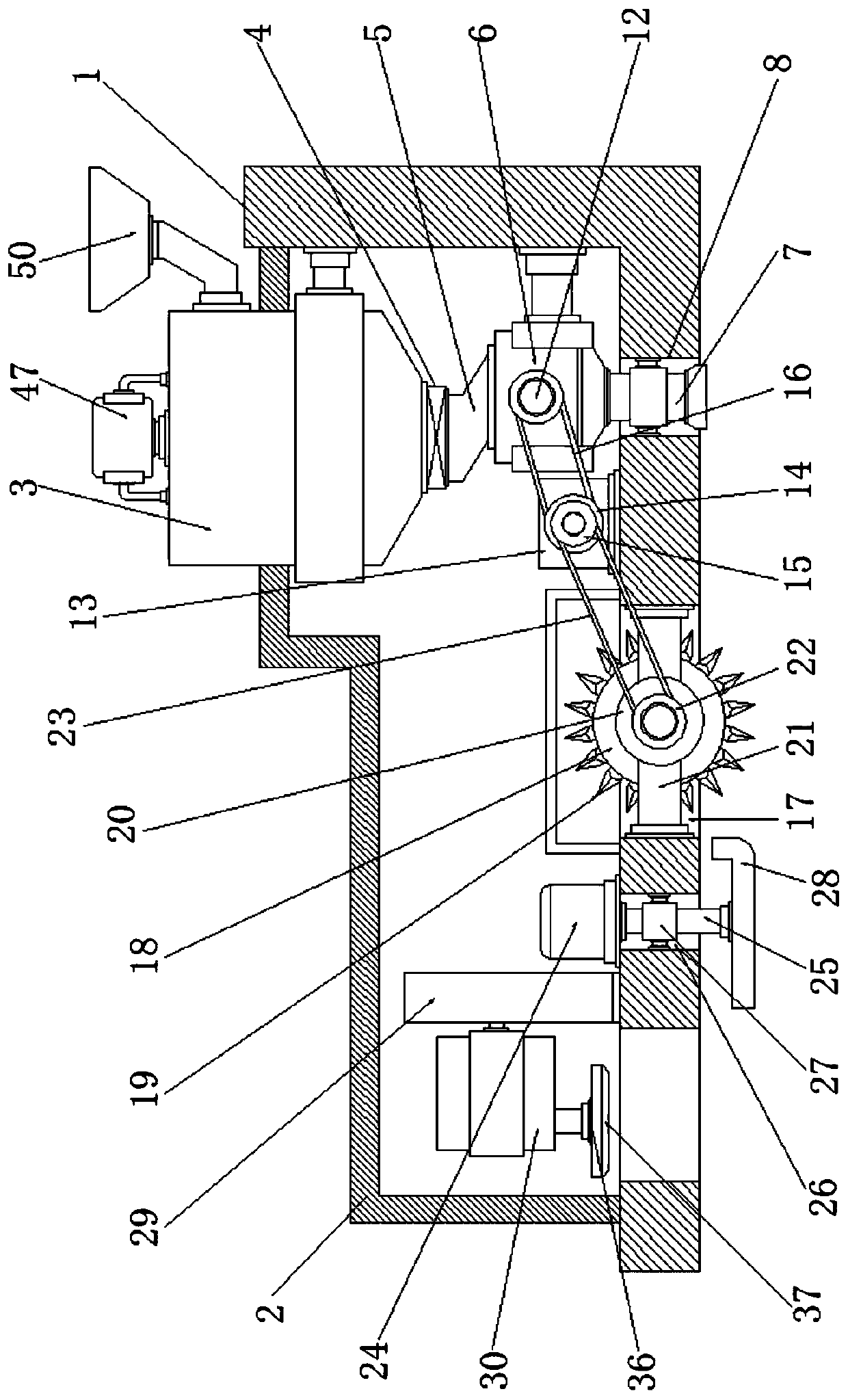
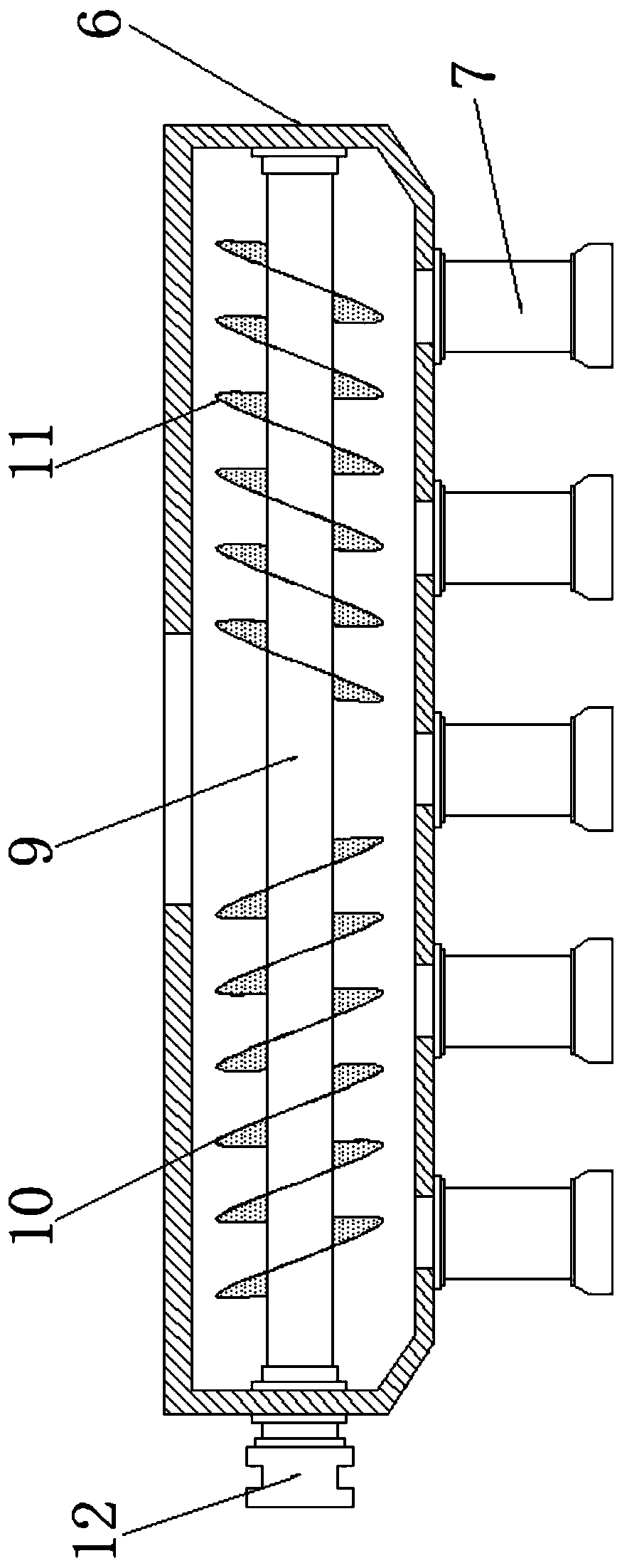
[0043] Embodiment one, such as Figure 1-10 As shown, a road bridge embankment pavement construction device according to an embodiment of the present invention includes a support base 1, a housing 2 is installed on the top of the support base 1, and a barrel 3 is installed on the top side of the housing 2, and the The bottom end of the barrel 3 runs through the shell 2 and extends to the inside of the shell 2, the bottom of the barrel 3 is equipped with an electromagnetic valve 4, and the bottom of the electromagnetic valve 4 is equipped with a connecting pipe 5, so The bottom of the connecting pipe 5 is equipped with a distributing bin 6, and the bottom of the distributing bin 6 is evenly equipped with a number of distributing pipes 7, and the position corresponding to the distributing pipe 7 on the support base 1 is provided with strips. Shaped groove one 8, and the bottom end of described distributing pipe 7 all runs through described strip groove one 8 and extends to the b...

Embodiment 2

[0044] Embodiment two, such as figure 1 , 2 , 8, the top of the barrel 3 is fixedly installed with a motor four 47, the bottom of the motor four 47 is equipped with a rotating shaft 48, and the bottom end of the rotating shaft 48 runs through and extends to the barrel 3 Inside, the outer side of the bottom end of the rotating shaft 48 is staggered with stirring rods 49, and the top of one side of the barrel 3 is equipped with a feed funnel 50; through the motor four 47 and the rotating shaft 48 And the interaction of the stirring rod 49 can stir the concrete to prevent it from solidifying, so that the laying operation can be better carried out, and the feeding funnel 50 is convenient to carry out the feeding operation better, and then It is convenient to better meet the needs of people.

Embodiment 3

[0045] Embodiment three, such as figure 1 , 9 As shown, a strip plate 51 is installed on the bottom of the support seat 1 and is located on the side of the strip groove one 8 close to the strip groove two 17, and the bottom of the strip plate 51 is evenly equipped with teeth Slice 52; through the strip plate 51 and the tooth sheet 52, the concrete can be better distributed, so that the concrete laying operation can be better performed, and the use needs of people can be better met.


PUM


Abstract

The invention discloses a highway bridge roadbed and pavement construction device and a construction method thereof. A shell is mounted at the top of a supporting seat; a material barrel is mounted onone side of the top of the shell; the bottom end of the material barrel penetrates through the shell and extends into the shell; an electromagnetic valve is mounted at the bottom of the material barrel; a connecting pipe is mounted at the bottom of the electromagnetic valve; a material distributing bin is mounted at the bottom of the connecting pipe; a plurality of material distributing pipes areuniformly mounted at the bottom of the material distributing bin; first strip-shaped grooves are formed in the positions, corresponding to the material distributing pipes, of the supporting seat; thebottom ends of the material distributing pipes penetrate through the first strip-shaped grooves and extend to the positions below the bottoms of the first strip-shaped grooves; a rotating rod is installed in the material distributing bin; a first spiral blade and a second spiral blade are installed on the rotating rod; a first rotating wheel is installed on the outer side edge of the material distributing bin; and one end of the rotating rod penetrates through the material distributing bin to be connected with the first rotating wheel.

Description

technical field [0001] The invention relates to the technical field of pavement construction, in particular to a construction device and a construction method for roadbed and pavement of highway bridges. Background technique [0002] With the vigorous development of the transportation industry, the replacement of roads and bridges is accelerating. The road surface is a layered structure that is layered on the roadbed with various road materials or mixtures for cars to drive. Its function is to ensure that cars It can run all-weather, stable, high-speed, comfortable, safe and economical on the road; currently, when carrying out road construction, the concrete is poured on the area to be paved by a concrete truck, and then the concrete is manually removed. Manual operation is slow and inefficient, and cannot achieve a better concrete laying effect, thereby affecting the quality of pavement construction, and thus cannot better meet people's use needs. [0003] To sum up, how t...

Claims


Application Information

Patent Timeline
Patent Type & Authority Applications(China)
IPC IPC(8): E01D21/00E01D19/08
CPCE01D21/00E01D19/08E01D19/083
Inventor 李春育张磊陈红冯小敏谢喜灵
Owner 李春育
Why Eureka
Try Eureka