
Construction method of vertical water stop structure of hydraulic engineering

A vertical water stop and construction method technology, applied in water conservancy projects, sea area projects, dams, etc., can solve the problems of water stop plate height adjustment, heavy workload, sealing bottom, etc., to increase the overall height and meet the water retaining requirements Effect

Inactive Publication Date: 2020-08-11
安徽派农生态农业有限公司
View PDF0 Cites 1 Cited by
  • Summary
  • Abstract
  • Description
  • Claims
  • Application Information

AI Technical Summary

Problems solved by technology

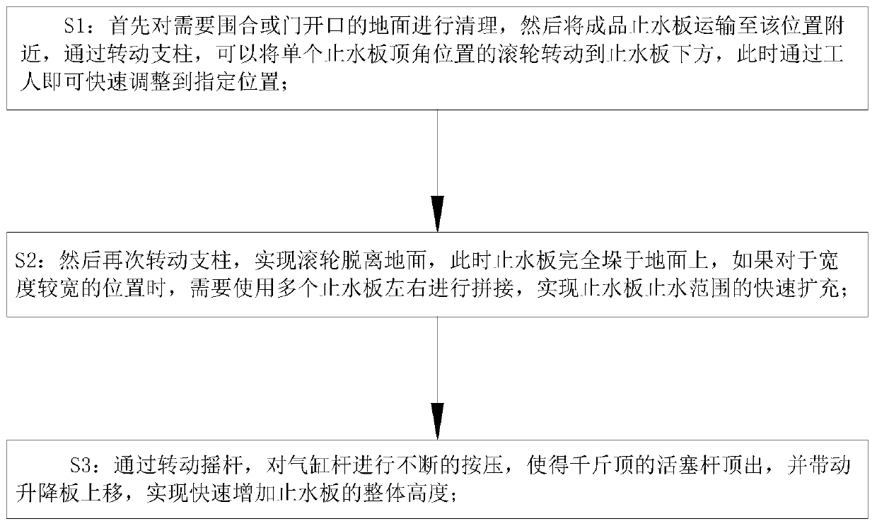
[0005] In order to make up for the deficiencies of the existing technology and solve the existing technology, the water stop board is only connected by simple splicing. On the one hand, the sealing performance is relatively low, and water seepage is prone to occur. At the same time, when the water level is high, it is difficult to quickly fix the water stop. The height of the board is adjusted, and the panel structure requires a large number of artificial temporary splicing, high technical requirements and a large workload, and it is difficult to meet the water-stop requirements of sudden problems. The present invention proposes a vertical water-stop structure for water conservancy projects construction method

Method used


Image

  • Construction method of vertical water stop structure of hydraulic engineering
  • Construction method of vertical water stop structure of hydraulic engineering
  • Construction method of vertical water stop structure of hydraulic engineering

Examples


Embodiment approach

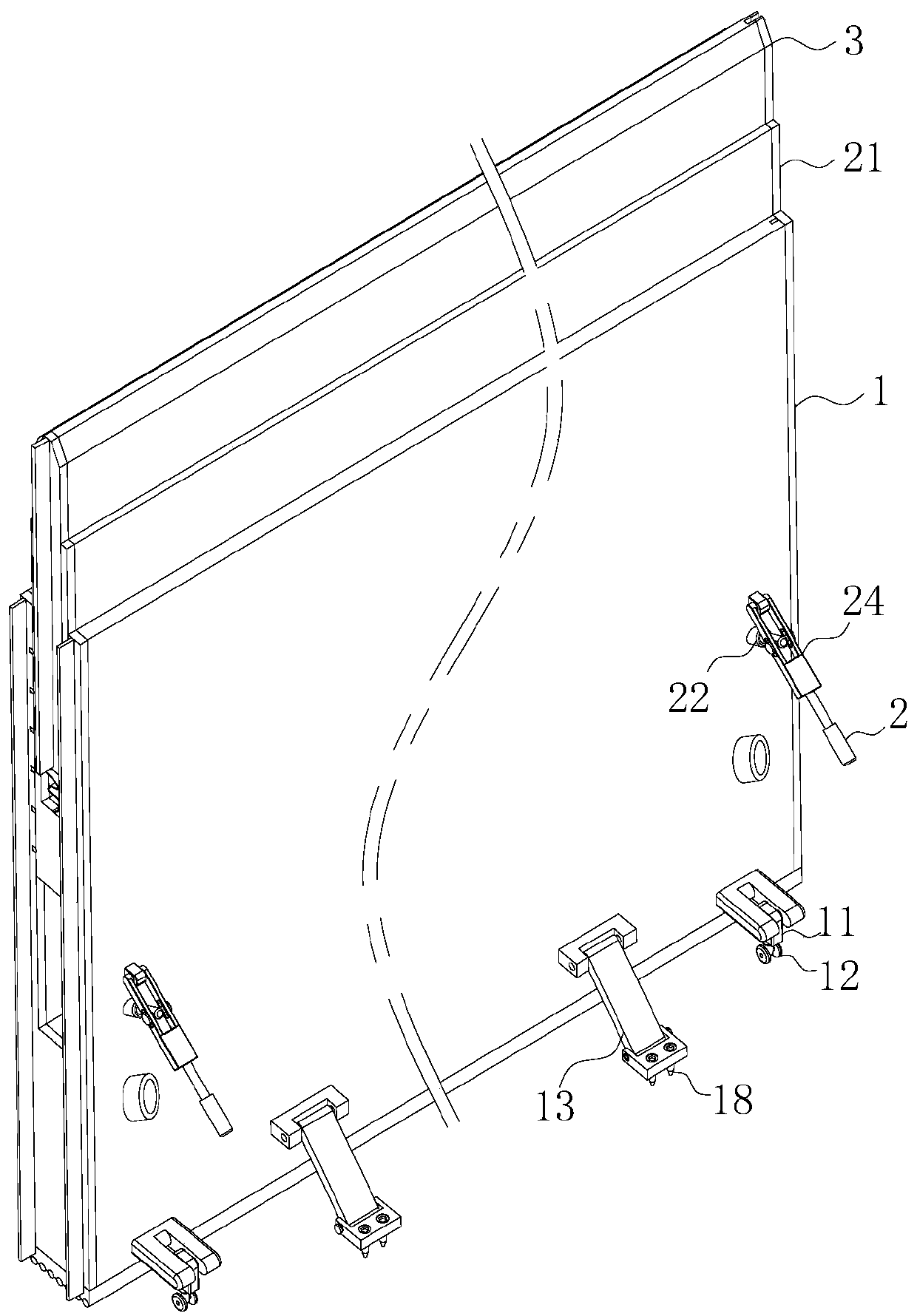
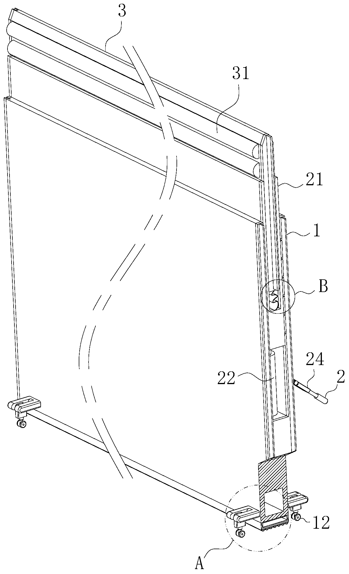
[0033] As an embodiment of the present invention, the upper surface of the lifting plate 21 is provided with a second chute; the inside of the second chute is slidingly connected with a light baffle 3 up and down; One side is fixedly connected with a strip-shaped floating column 31; the inside of the floating column 31 is provided with a cavity, and the inside of the cavity is filled with light gas; during operation, when the flood rises rapidly, due to the lifting plate 21 The height needs to be adjusted by the operator. When the operator is doing other work, he has not observed the change of the flood water level in time, so it is easy for the flood to overflow the water stop plate and the problem of backflow, and once this problem occurs At this time, it is more difficult to carry out remediation, and it is difficult to perform effective operation in the case of a large amount of water flow to realize the height adjustment of the lifting plate 21. Therefore, by setting the f...


PUM


Abstract

The invention belongs to the technical field of vertical water stop, and particularly relates to a construction method of a vertical water stop structure of hydraulic engineering. Water stop plates adopted in the method comprise substrates, rocking bars and light baffles. First sliding grooves are formed in the upper surfaces of the substrates. Lifting plates are in sliding connection in the firstsliding grooves. Jacks are fixedly connected between the lower surfaces of the lifting plates and the groove bottoms of the first sliding grooves. The surfaces of the substrates are fixedly connectedwith fixed blocks. The positions, under the fixed blocks, of the substrates are fixedly connected with air cylinder bars. Connecting bars are connected between the air cylinder bars and the fixed blocks. The rocking bas are fixedly connected to the surfaces of the connecting bars. Second sliding grooves are formed in the upper surfaces of the lifting plates. The light baffles are in sliding connection in the second sliding grooves. By means of the construction method, the height of the water stop plates can be rapidly adjusted effectively, the requirements of water stop of different grades offlood disasters are greatly met, integrality is high, transporting and adjusting are convenient, and the process that professionals carry out professional splicing operation is not needed.

Description

technical field [0001] The invention belongs to the technical field of vertical water stop, in particular to a construction method for a vertical water stop structure of a water conservancy project. Background technique [0002] When there is a flood or when the precipitation is large, because the rainwater cannot be discharged quickly in a short period of time, it is easy to cause backflow in the houses of the residents on the first floor, which poses a threat to the lives and property of the residents on the first floor, especially for the shops on the first floor of the city streets. When the rainwater is heavy, the rainwater that is not discharged in time in the street will be poured into the shops, which will cause huge economic losses to the shop owners on the first floor. [0003] In the prior art, the water stop boards are only connected by simple splicing. On the one hand, the sealing performance is relatively low, and water seepage is prone to occur. At the same ti...

Claims


Application Information

Patent Timeline
IPC IPC(8): E02B3/10E02B3/16
CPCE02B3/106E02B3/16
Inventor 朱金强周伟华林胜男
Owner 安徽派农生态农业有限公司
Learn More