
Efficient evaporator of separated gravity assisted heat pipe

A gravity heat pipe, separated technology, applied in the field of heat pipes, can solve the problems of large size, large surface area, large difference in condensate mass flow rate, etc.

Pending Publication Date: 2020-08-11
庞苏佳
View PDF8 Cites 0 Cited by
  • Summary
  • Abstract
  • Description
  • Claims
  • Application Information

AI Technical Summary

Problems solved by technology

Its defect is: when the liquid level of the condensate in the liquid inlet pipe is at a certain height, the U-shaped evaporation tubes of several paths below the liquid level of the condensate are flooded evaporation heat exchange, and the U-shaped evaporation pipes of several paths above the liquid level of the condensate U-shaped evaporating tube has no phase change heat
However, in the "automatic liquid separator", the condensate in a saturated state is partially vaporized into steam due to heat absorption, and the vaporized steam gathers in the cavity of the "automatic liquid separator", and the subsequent condensate cannot be normal. Enter the "automatic liquid dispenser", the "building flat plate split wall-mounted vacuum solar superconducting heat collection device" can not operate normally
[0008] The Chinese patent "evaporator of a separate gravity heat pipe" (application number CN201420051601), the defect of this patent is: each evaporation tube passes through the cavity of the "collecting pipe", which will cause the "collecting pipe" cavity More condensate vaporizes; the "collection pipe" has a large size and a large surface area, and it is easier to absorb external heat, resulting in more condensate vaporization in the "collection pipe" cavity, so more air guide pipes need to be installed; When inclined, the mass flow rate of the condensate entering the highest evaporator tube is quite different from that of the condensate entering the lowest evaporator tube; the evaporator tubes described in this patent cannot be arranged horizontally

Method used


Image

  • Efficient evaporator of separated gravity assisted heat pipe
  • Efficient evaporator of separated gravity assisted heat pipe
  • Efficient evaporator of separated gravity assisted heat pipe

Examples


Embodiment Construction

[0088] Below in conjunction with the embodiment of accompanying drawing, the present invention will be further described:

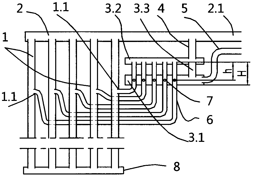
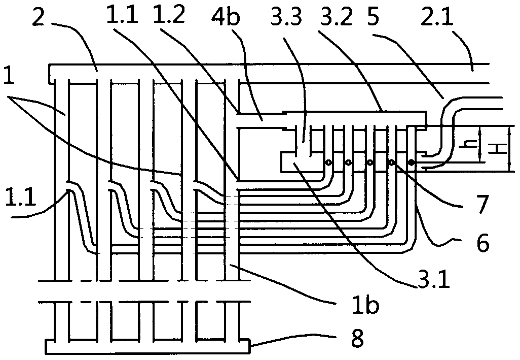
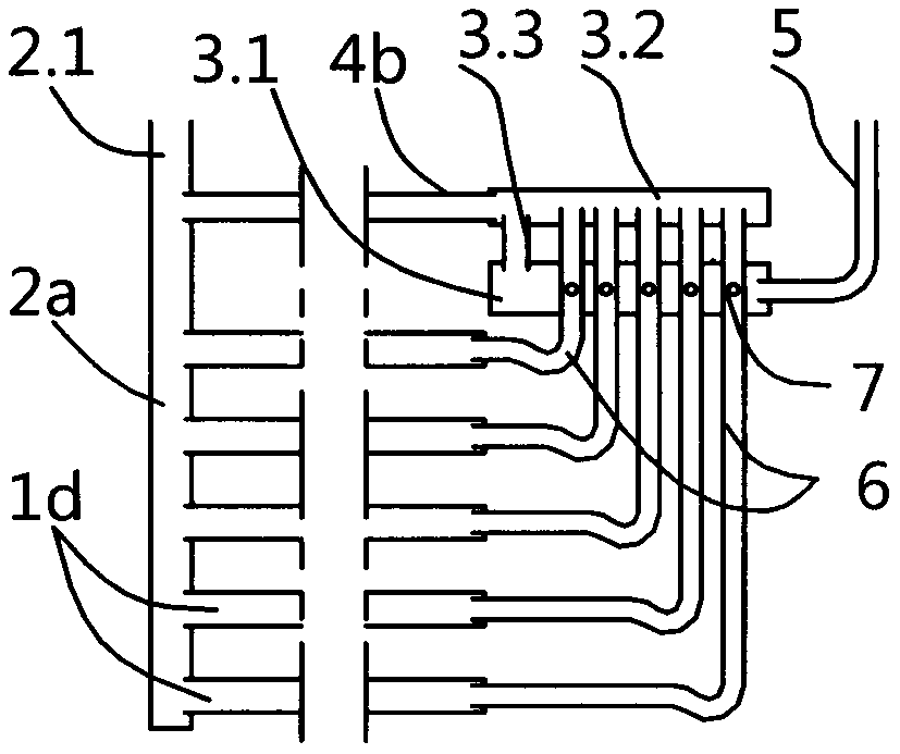
[0089] attached figure 1 It is the first embodiment of the present invention, one of the first preferred pipeline principles of the technical solution: including a horizontal steam header 2, including two or more vertical or oblique evaporation tubes 1, A condensate inlet pipe 5; one end of the steam header 2 is sealed and the other end is provided with a steam outlet 2.1; the lower wall of the steam header 2 is provided with a through hole to facilitate the communication between the evaporation pipe 1 and the flash conduit 4; The upper tube wall of the evaporating tube 1 is provided with a liquid inlet hole 1.1, and the upper nozzles of the evaporating tube 1 are connected with the steam manifold 2; the lower nozzles of the evaporating tube 1 are connected with the lower connecting pipe 8; the key is: The uniform distribution of condensate is completed ...


PUM


Abstract

The invention discloses an efficient evaporator of a separated gravity assisted heat pipe, and belongs to the heat pipe technology. According to the evaporator, evaporation pipes can be vertically orobliquely arranged, and can also be horizontally-arranged pipes or coiled pipes; a special distribution mechanism enables condensate to uniformly enter the upper parts of the horizontally-arranged evaporation pipes to form falling film evaporation, and the upper pipe walls and the lower pipe walls of the evaporation pipes have phase change heat exchange, it is guaranteed that the condensate can beevenly distributed to all paths of horizontally-arranged evaporation pipes or coiled evaporation pipes with different heights, and it is guaranteed that all paths of evaporation pipes with differentheights have phase-change heat exchange; flash evaporation gas generated in a cavity of the distribution mechanism is guided out in time and cannot be gathered in the cavity of the distribution mechanism, and therefore normal operation of a separated heat pipe system adopting the evaporator is guaranteed; and even if the evaporator is obliquely arranged, the mass flow of the condensate entering all paths of evaporation pipes is almost uniform.

Description

technical field [0001] The invention belongs to heat pipe technology, in particular to a heat pipe evaporator. Background technique [0002] The existing separated gravity heat pipe at least includes a condenser, an evaporator, a steam pipe, and a liquid return pipe. [0003] The evaporators of the existing separated gravity heat pipes include coil evaporators and grid evaporators. But all have flaws: [0004] Coiled tube evaporator. Each serpentine tube has multiple horizontal evaporation tubes in the vertical direction, and the adjacent evaporation tubes are connected by elbows. The liquid inlet of each coil is at the mouth of an evaporation tube at the lowest point of the evaporator, and the steam outlet of each coil is at the mouth of an evaporation tube at the highest point of the evaporator. Its defect is obvious: when the liquid level of the condensate in the liquid return pipe is at a certain height, in each coil pipe, several evaporator tubes below the liquid le...

Claims


Application Information

Patent Timeline
Patent Type & Authority Applications(China)
IPC IPC(8): F28D15/02
CPCF28D15/0266
Inventor 不公告发明人
Owner 庞苏佳
Learn More