
Display device and polarizer

A technology for display devices and polarizers, which can be applied to identification devices, optics, optical components, etc., and can solve problems such as affecting the effect of taking pictures.

Inactive Publication Date: 2020-08-11
BOE TECH GRP CO LTD +1
View PDF9 Cites 15 Cited by
  • Summary
  • Abstract
  • Description
  • Claims
  • Application Information

AI Technical Summary

Problems solved by technology

This will affect the photo effect

Method used


Image

  • Display device and polarizer
  • Display device and polarizer
  • Display device and polarizer

Examples


Embodiment Construction

[0024] In order to enable those skilled in the art to better understand the technical solutions of the present invention, the present invention will be further described in detail below in conjunction with the accompanying drawings and specific embodiments.

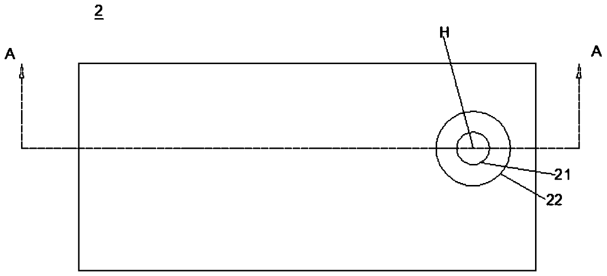
[0025] refer to Figure 2a-Figure 2c , the embodiment of the present disclosure provides a polarizer 2, the polarizer 2 has a first surface 2a and a second surface 2b parallel to the plane where it is located, the polarizer 2 has a pass through the first surface 2a and the second surface 2b The hole H, the boundary formed by the through hole H on the first surface 2a is the first boundary 21, the boundary formed by the through hole H on the second surface 2b is the second boundary 22, and the first boundary 21 is on the plane where the second surface 2b is located. The orthographic projection is located inside the second boundary 22 and is not in contact with the second boundary 22; for the boundary formed by the through ...


PUM


Abstract

The invention provides a display device and a polarizer. In the display device, the polarizer is provided with a first surface and a second surface which are parallel to a plane where the polarizer islocated. The polarizer is provided with a through hole penetrating through the first surface and the second surface, the boundary formed by the through hole on the first surface is a first boundary,the boundary formed by the through hole on the second surface is a second boundary, and the orthographic projection of the first boundary on the plane where the second surface is located is located onthe inner side of the second boundary and does not make contact with the second boundary. For the boundary formed by the through hole on any two planes parallel to the plane where the polarizer is located, the orthographic projection of the boundary close to the first surface on the plane where the boundary far away from the first surface is located does not exceed the boundary far away from thefirst surface. By applying the display device, the problem of bubbles when a via hole is filled with a liquid optical adhesive can be solved.

Description

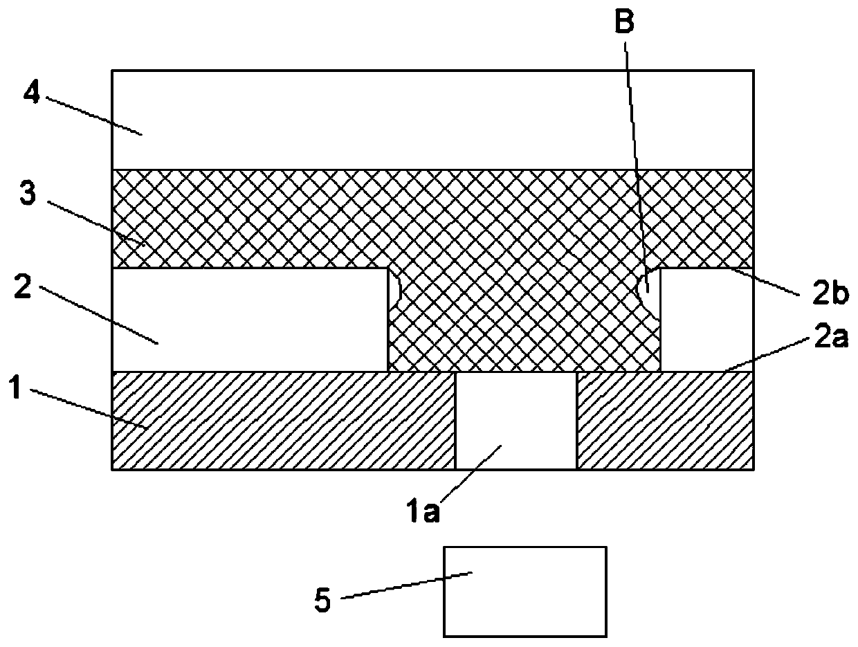
technical field [0001] The present disclosure relates to the field of display technology, and more particularly, to a display device and a polarizer. Background technique [0002] In the related art, in order to realize full-screen display, it is necessary to set transparent holes on the edge of the display area of ​​the display panel (such as notch screen, water drop screen, etc.) or in the display area, so that the camera placed on the back of the display panel can obtain the image. refer to figure 1 , the front of the display panel 1 is provided with a polarizer 2 , an optical glue 3 , and a cover 4 in sequence. In order to realize the camera function, the area where the display panel 1 is opposite to the camera 5 is a transparent area 1a, and the area where the polarizer 2 is opposite to the camera 5 is drilled (to avoid the attenuation of the external light by the polarizer 2), and the polarizer is realized by liquid optical glue 3. 2 and the fit between the cover pl...

Claims


Application Information

Patent Timeline
Patent Type & Authority Applications(China)
IPC IPC(8): G09F9/33
CPCG09F9/33H10K59/65H10K59/8791G02B5/3025H10K50/868
Inventor 张家祥王康刘晓霞杨皓天杨俊辉谢扶政张斌
Owner BOE TECH GRP CO LTD
Learn More