
Method for winding tape

A technology of reel and adhesive tape, applied in the field of tape winding, to achieve the effect of suppressing product defects and improving yield

Active Publication Date: 2011-05-25
RESONAC CORPORATION
View PDF1 Cites 1 Cited by
  • Summary
  • Abstract
  • Description
  • Claims
  • Application Information

AI Technical Summary

Problems solved by technology

[0005] However, the inventors of the present invention have repeatedly studied and found that when producing an anisotropic conductive film, the film material coated to form an adhesive layer is cut in a narrow width and wound on a reel, and this production method There are still problems that need to be improved

Method used


Image

  • Method for winding tape
  • Method for winding tape
  • Method for winding tape

Examples


Embodiment Construction

[0022] Hereinafter, the best mode for carrying out the present invention will be described with reference to the drawings.

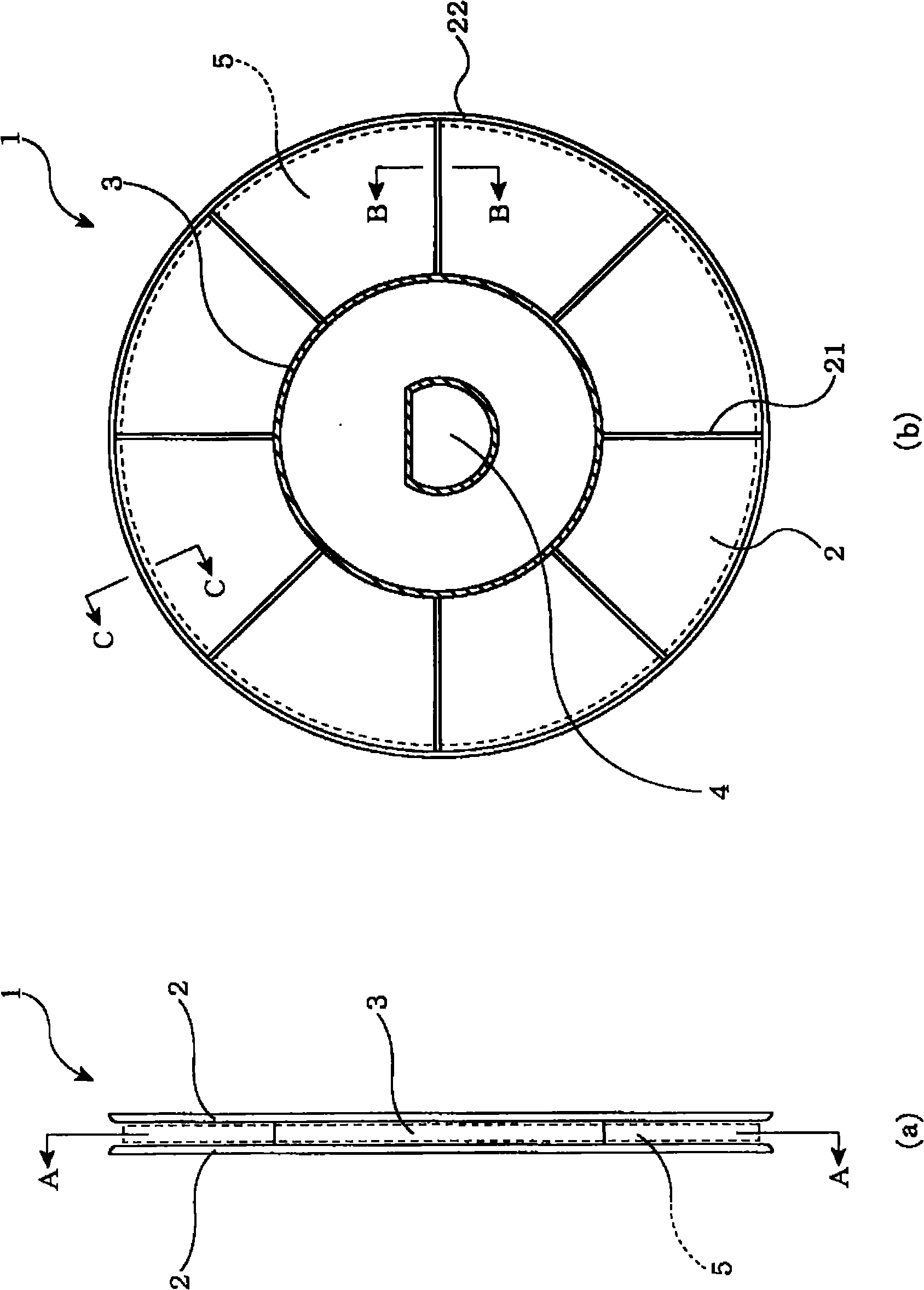
[0023] in addition, figure 1 It is a schematic explanatory drawing which shows the reel used for the tape winding method of this embodiment. figure 1 (a) is the front view, figure 1 (b) is figure 1 (a) A-A sectional view.

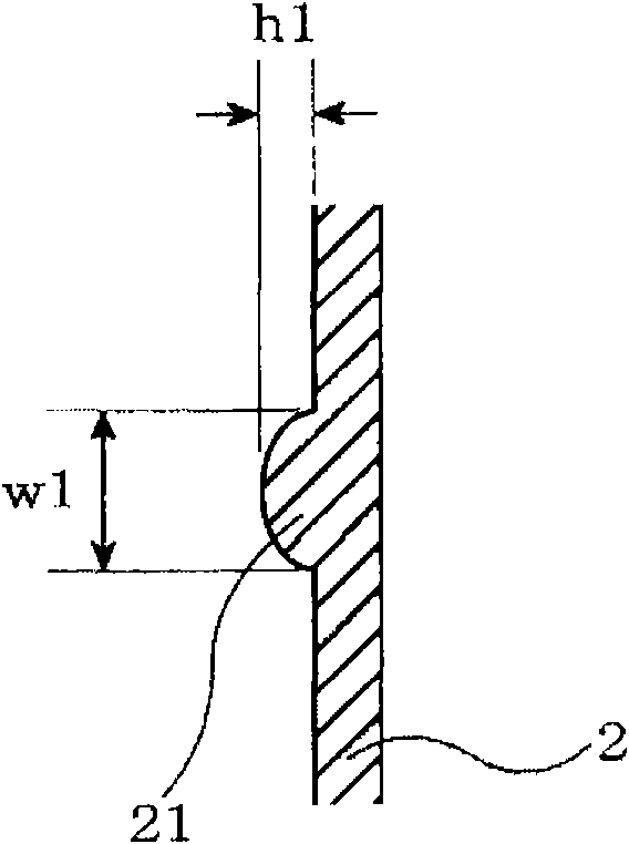
[0024] figure 1 The illustrated reel 1 includes a cylindrical winding portion 3 and a pair of side plate portions 2 , 2 mounted oppositely across the winding portion 3 in parallel or substantially in parallel. In addition, substantially in the center of the reel 1, a shaft hole 4 in the shape of a D hole is penetratingly provided. By inserting a winding shaft of a winding device (not shown) into the shaft hole 4, the reel 1 is attached to the reel. On the winding device, it rotates with the drive of the winding shaft.

[0025] The reel 1 of this structure is used to cut the film material coated with the adhesive layer into a nar...


PUM

PropertyMeasurementUnit
heightaaaaaaaaaa
widthaaaaaaaaaa
heightaaaaaaaaaa

Abstract

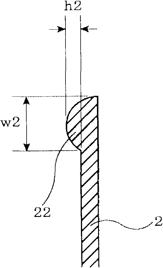
Disclosed is a reel comprising a columnar wind-up unit (3) and a pair of side plates (2, 2) arranged parallel or roughly parallel to each other with the wind-up unit (3) being sandwiched between them. The inner surface of the peripheral portion of at least one side plate (2) is provided with a peripheral projection (22).

Description

[0001] This application is a divisional application of the invention patent application with the application number 200780022858.6, the application date being June 14, 2007, and the invention name being "reel". technical field [0002] The present invention relates to a tape winding method for winding an adhesive tape or an adhesive tape formed by cutting a film material formed with an adhesive layer or an adhesive layer into narrow strips on a reel. Background technique [0003] In recent years, the anisotropic conductive film composed of conductive particles in the adhesive layer formed on the base material is mostly used in the circuit connection of liquid crystal displays and the like. This anisotropic conductive film is shown in patent As described in Document 1 etc., generally, after forming an adhesive layer or the like by coating on a wide film material, it is cut into narrow strips and wound up on a roll for manufacture and supply. [0004] Patent Document 1: Japane...

Claims


Application Information

Patent Timeline
Patent Type & Authority Applications(China)
IPC IPC(8): B65H75/14B65H75/18
CPCB65H75/14B65H2301/41368B65H2701/377B65H54/12B65H75/08
Inventor 越智敬人关贵志
Owner RESONAC CORPORATION
Learn More