Heat exchanger and manufacturing method thereof

A technology for heat exchangers and heat transfer fins, used in heat exchanger sealing devices, heat exchange equipment, heat exchanger types, etc., can solve problems such as unsuitable sealing and deformation, and achieve easy and reliable control of poor coating. Effect of airtight retention effect

Active Publication Date: 2017-12-29
SEIBU GIKEN CO LTD
View PDF10 Cites 1 Cited by
  • Summary
  • Abstract
  • Description
  • Claims
  • Application Information

AI Technical Summary

Problems solved by technology

However, the pressurization performed simultaneously with this heating has the problem that it is not suitable for the method of sealing the side surface of a specific heat exchange laminate in which a plurality of Thin heat transfer sheets are laminated and may deform if excessive external force is applied to that particular heat exchange laminate

Method used


Image

  • Heat exchanger and manufacturing method thereof
  • Heat exchanger and manufacturing method thereof
  • Heat exchanger and manufacturing method thereof

Examples


no. 1 approach

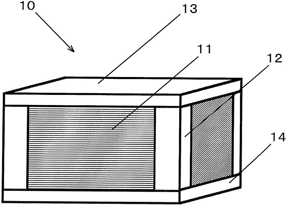
[0041] Below, refer to Figure 1 to Figure 8 The heat exchanger according to the first embodiment of the present invention will be described. The heat exchange laminate 11 is formed by laminating a plurality of heat transfer sheets 16 such as aluminum sheets. In addition, the heat exchange laminate 11 is assembled to a housing by bolts, rivets, or the like, and the housing is composed of a corner member 12, a top plate 13, and a bottom plate 14 made of metal. In addition, as the heat transfer sheet 16, in addition to the aluminum sheet, especially when the air for heat exchange contains corrosive substances, a corrosion-resistant coated aluminum sheet or stainless steel sheet can also be used. Corrosive metal sheet.

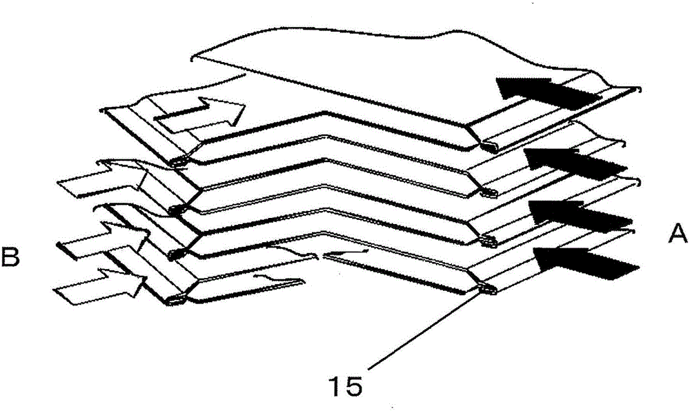
[0042] figure 2 A schematic diagram of the heat exchange laminate 11 is shown. The airflow A of the return air and the airflow B of the outside air are completely isolated by the heat transfer sheet, and no gas transfer occurs. In addition, such as image 3 As ...

no. 2 approach

[0053] Picture 9 The heat exchanger of another embodiment is shown. This heat exchanger is a cross-type heat exchanger in which flat heat transfer fins and heat transfer fins processed in a wave form as a spacer are stacked alternately and orthogonally. In this heat exchanger, as in the first embodiment described above, the unvulcanized rubber 18 provided between the heat exchange laminate 11 and the corner member 12 is heated to ensure an airtight state.

[0054] In addition, although in the first embodiment, the notch of the joint portion between the corner member 12 and the corner portion of the heat exchange laminate 11 is formed as Picture 10 The shape shown in (a), but not limited to this, can be formed as Picture 10 Various shapes shown in (b) to (f). Furthermore, shapes other than the above-mentioned shapes can also be appropriately adopted.

[0055] The heat exchanger of the present invention is manufactured by the above method, and can be used as a heat exchanger in s...


PUM


Abstract

The invention provides a heat exchanger which can perform heat exchange too in occasions where silicon-containing materials cannot be used. A corner member (12), a top plate (13) and a bottom plate (14) fix a heat exchange laminating body (11). Unvulcanized rubber mixed with a vulcanizing agent is inserted into a joint part between the corner member (12) and the corner portion of the heat exchange laminating body (11). The unvulcanized rubber is heated, so that the unvulcanized rubber is vulcanized to form, so that the rubber is expanded. Therefore, the airtightness keeping effect of the heat exchanger can be improved within a short time, and the heat exchanger can be easily manufactured, namely, the heat exchanger can be used too in a coating plant where silicon-containing materials cannot be used.

Description

Technical field [0001] The present invention relates to a static heat exchanger and a manufacturing method thereof. Background technique [0002] When ventilating in a drying furnace or the like of a factory, if the heat of the exhaust gas discharged from the drying furnace or the like is recovered by a heat exchanger, the energy loss can be reduced, and the energy saving effect can be improved. In other words, the high-temperature exhaust gas from the drying furnace of the factory is exchanged with room temperature air such as outside air, and the outside air whose temperature rises is supplied to the drying oven, etc., thereby saving energy for heating the outside air . [0003] As such a heat exchanger used in factories or machinery, it is preferable to use a cross-type heat exchanger formed by laminating aluminum heat transfer fins in consideration of heat recovery efficiency. As such a heat exchanger, a heat exchanger formed by stacking rectangular heat transfer fins is know...

Claims


Application Information

Patent Timeline
Patent Type & Authority Applications(China)
IPC IPC(8): F28D9/00F28F3/10F28F11/02
CPCF28D9/00F28F3/10F28F11/02
Inventor 冈野浩志河边希篠原修二藤田淳一
Owner SEIBU GIKEN CO LTD
Why Eureka
Try Eureka