A cooling box and a switchgear

A switch cabinet and box body technology, applied in substation/switch layout details, substation/switchgear cooling/ventilation, electrical components, etc., can solve problems such as overheating of electrical components, hazards of electrical components, and large power consumption

Active Publication Date: 2021-11-02
GUANGDONG POWER GRID CO LTD DONGGUAN POWER SUPPLY BUREAU
View PDF8 Cites 0 Cited by
  • Summary
  • Abstract
  • Description
  • Claims
  • Application Information

AI Technical Summary

Problems solved by technology

[0002] The switchgear is a kind of electrical equipment. There are many electrical components inside the switchgear. These electrical components will release a lot of heat during the working process. If the heat cannot be discharged from the switchgear, the internal temperature of the switchgear will rise. , causing electrical components to overheat and break down, and the general heat dissipation method is to set louvers in the switch cabinet and add a cooling fan to discharge the heat in the switch cabinet. Contrary to the concept, at the same time, the cooling fan will send dust to the inside of the switch cabinet while blowing air, causing great harm to electrical components

Method used


Image

  • A cooling box and a switchgear
  • A cooling box and a switchgear
  • A cooling box and a switchgear

Examples


Embodiment 1

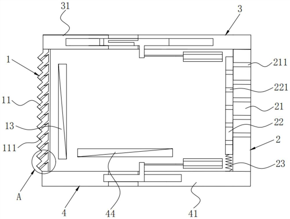
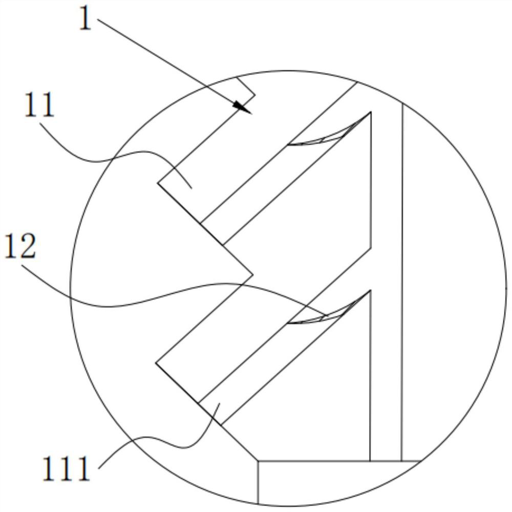
[0037] Such as Figure 1 to Figure 6 The heat dissipation box shown includes a housing, a primary heat dissipation assembly 1 and a secondary heat dissipation assembly 2; the casing is used to accommodate heat generating devices; The heat dissipation assembly 1 includes a first-level heat dissipation plate 11, and the first-level heat dissipation plate 11 is provided with a first-level heat dissipation hole 111, and the first-level heat dissipation hole 111 outputs the heat inside the housing to the outside; the second-level heat dissipation assembly 2 Installed on the housing, the secondary heat dissipation assembly 2 includes a secondary fixed plate 21, a secondary moving plate 22 and a deformation member 23, and the secondary moving plate 22 and deformation member 23 are located on the secondary fixing plate 21 On the inner side, one end of the deformation member 23 is connected to the inner wall of the housing, and the other end of the deformation member 23 is connected to...


PUM


Abstract

The invention belongs to the technical field of electrical heat dissipation equipment, and discloses a heat dissipation box, which includes a shell, a primary heat dissipation component and a secondary heat dissipation component; the primary heat dissipation component includes a primary heat dissipation plate, and the primary heat dissipation plate is provided with a primary heat dissipation hole , the first-level heat dissipation holes output the heat inside the shell to the outside; the second-level heat dissipation assembly includes a second-level fixed plate, a second-level moving plate and a deformable part, the second-level moving plate and the deformable part are located on the inner side of the second-level fixed plate, and the deformable part One end is connected to the inner wall of the shell, and the other end of the deformed part is connected to the secondary moving plate. The secondary moving plate is provided with a connection hole, and the secondary fixed plate is provided with a secondary cooling hole. The secondary moving plate is driven to move on one side of the secondary fixing plate, and the connecting hole of the secondary moving plate can be connected to the secondary cooling hole of the secondary fixing plate to connect the outside world and the inside of the shell. The switchgear of the present application adopts the above-mentioned heat dissipation box, and realizes multiple heat dissipation and dustproof functions through multi-stage heat dissipation components.

Description

technical field [0001] The invention belongs to the technical field of electric cooling equipment, and in particular relates to a cooling box and a switch cabinet. Background technique [0002] The switchgear is a kind of electrical equipment. There are many electrical components inside the switchgear. These electrical components will release a lot of heat during the working process. If the heat cannot be discharged from the switchgear, the internal temperature of the switchgear will rise. , causing electrical components to overheat and break down, and the general heat dissipation method is to set louvers in the switch cabinet and add a cooling fan to discharge the heat in the switch cabinet. The concept is contrary to the concept. At the same time, the cooling fan will send the dust to the inside of the switch cabinet while blowing air, which will cause great harm to the electrical components. Contents of the invention [0003] The purpose of the present invention is to ...

Claims


Application Information

Patent Timeline
Patent Type & Authority Patents(China)
IPC IPC(8): H02B1/56H02B1/46
CPCH02B1/46H02B1/565
Inventor 赵留义冯永亮黎其芬陈浩超
Owner GUANGDONG POWER GRID CO LTD DONGGUAN POWER SUPPLY BUREAU
Why Eureka
Try Eureka