Dural repair device
A dura mater and equipment technology, applied in the field of dura mater repair equipment, can solve the problem of destroying the intention of minimally invasive surgery
- Summary
- Abstract
- Description
- Claims
- Application Information
AI Technical Summary
Problems solved by technology
Method used
Image

Examples
example 1
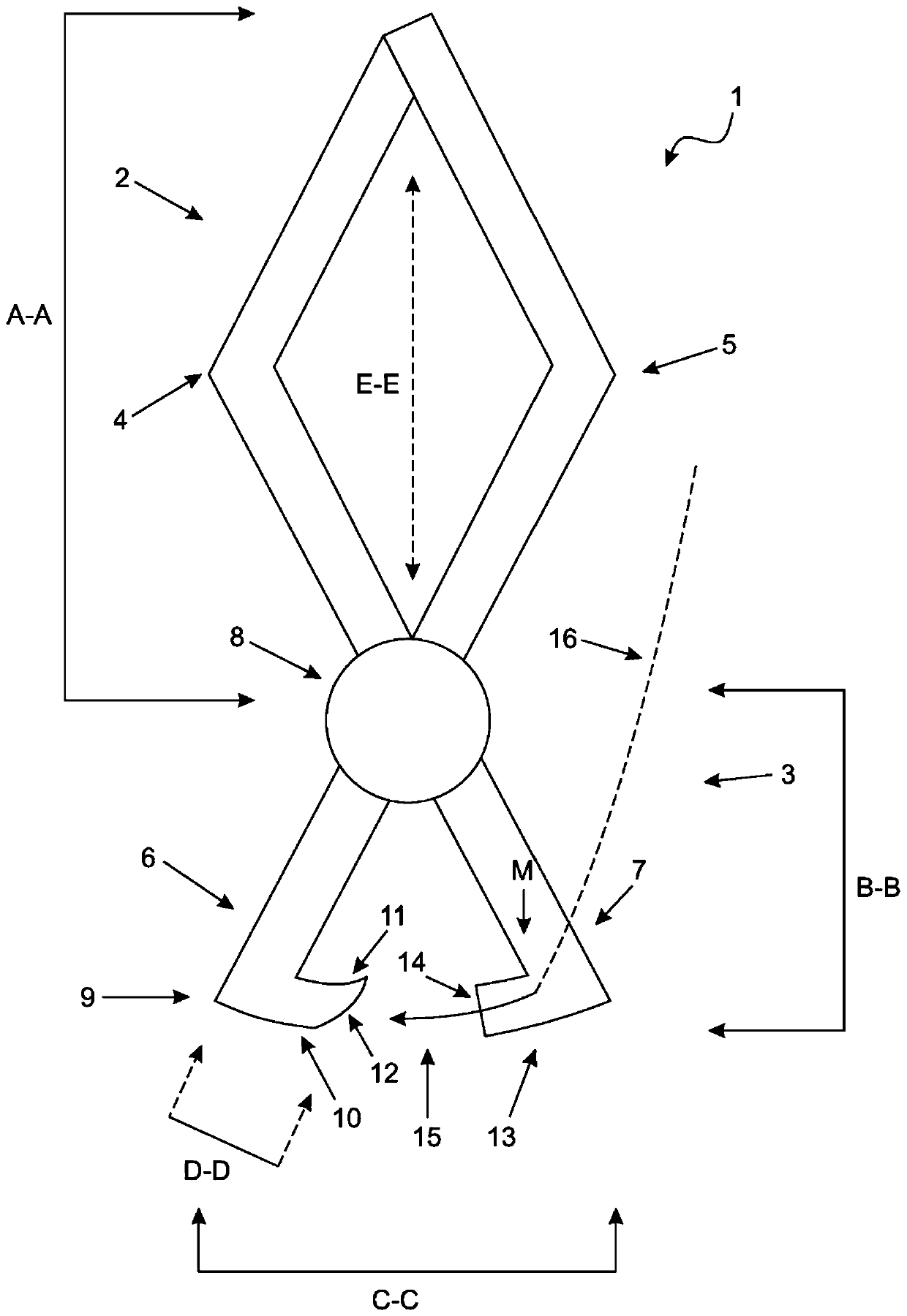
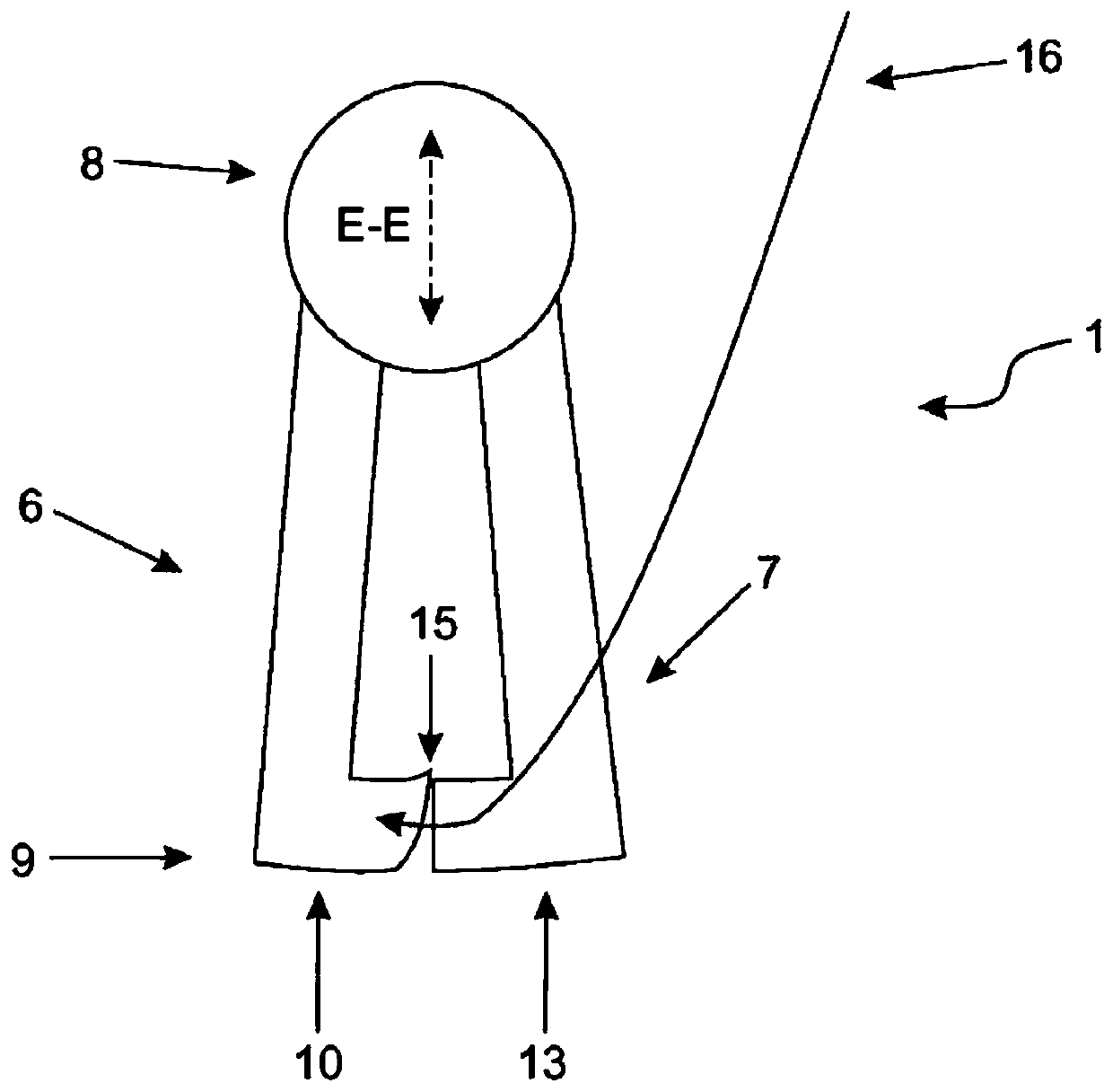
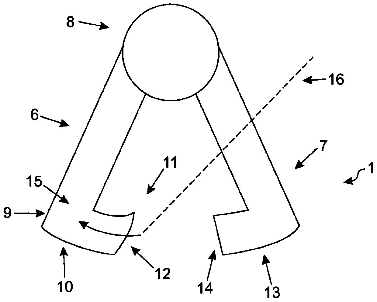
[0040] Example 1: Device mount. In a particular embodiment, the complete device 1 is pre-installed with Type suture 16 and needle 15. When the handle is squeezed, the needle 15 meets the platform 10 , or the needle 15 can be free and then moved by separate forceps or captured by the catch of the inner arm 6 . At least a portion of the inner arm 7 slides under the edge of the dura mater 17 to push the rootlet 21 and has a groove that mates with and captures or holds the needle 15 . Squeeze the handles and bring the two upper arms 4 and 5 together. During the repair, the needle 15 is protected and the rootlet 21 cannot be caught by the needle 15 and / or a portion of the suture 16 .
[0041] Sutures used in the methods and devices as described herein may comprise one or a combination of one or more of monofilament, multifilament synthetic, biological, absorbable and / or non-bioabsorbable sutures. Non-limiting examples of monofilament sutures include and / or II Polydioxano...
example 2
[0043] Example 2: The dura is partially torn, but CSF does not leak from the spinal canal. Small roots float and are next to the repair site. If the cerebrospinal fluid is drained, the rootlet will sink and the repair will be easier, but the methods presented here can be used to repair the original partial tear rather than complete the tear and then repair the tear. The methods provided herein allow for the repair of tears where the cerebrospinal fluid is not drained during the repair process. At least a portion of the inner arm 6, such as the platform 10, can be used to safely push the nerve, rootlet, or portion of the spinal cord away from the device so that even when the nerve, rootlet, or portion of the spinal cord is floating in the cerebrospinal fluid, the suture 15 Or the needle 16 will not touch or otherwise damage them.
[0044] this is in Figure 5 shown in Figure 5 The dura mater 17, tear opening 18, rootlet 21 and space containing cerebrospinal fluid 22 are sh...
example 3
[0046] Example 3: Repairing the dura creates a tear at the edge of the anatomy where the needle snags a rootlet when moved with too much force. The methods described herein may be used when the torn dura mater includes a tear on the bony sidewall of the spinal canal. this is in Figure 9 As shown in , the tear opening 18 of the dura mater 17, the rootlet 21, the space containing the cerebrospinal fluid 22, and the bony side wall 23 of the spinal canal are shown. With current techniques, there is a risk of injury due to forceful movement of the needle that can snag small roots. In the presently outlined embodiments, the rootlets will be preserved and in some cases no cerebrospinal fluid drainage will be required. It is contemplated that during the repair described herein, drainage of CSF or removal of small amounts of CSF may be performed, but other embodiments are contemplated that do not require fluid removal; than, less fluid removal will be required. When repairing the ...
PUM
| Property | Measurement | Unit |
|---|---|---|
| Length | aaaaa | aaaaa |
Abstract
Description
Claims
Application Information
 - R&D
- Intellectual Property
- Life Sciences
- Materials
- Tech Scout
- Unparalleled Data Quality
- Higher Quality Content
- 60% Fewer Hallucinations
Browse by: Latest US Patents, China's latest patents, Technical Efficacy Thesaurus, Application Domain, Technology Topic, Popular Technical Reports.
© 2025 PatSnap. All rights reserved.Legal|Privacy policy|Modern Slavery Act Transparency Statement|Sitemap|About US| Contact US: help@patsnap.com