Asymmetric mitral annuloplasty band

A technology of mitral valve and forming belt, which is applied in the direction of valve annulus, heart valve, medical science, etc., can solve problems such as valve defects

Active Publication Date: 2020-08-14
EDWARDS LIFESCIENCES LLC
View PDF22 Cites 0 Cited by
  • Summary
  • Abstract
  • Description
  • Claims
  • Application Information

AI Technical Summary

Problems solved by technology

Alternatively, the valve may be defective at birth or due to acquired disease

Method used


Image

  • Asymmetric mitral annuloplasty band
  • Asymmetric mitral annuloplasty band
  • Asymmetric mitral annuloplasty band

Examples


Embodiment Construction

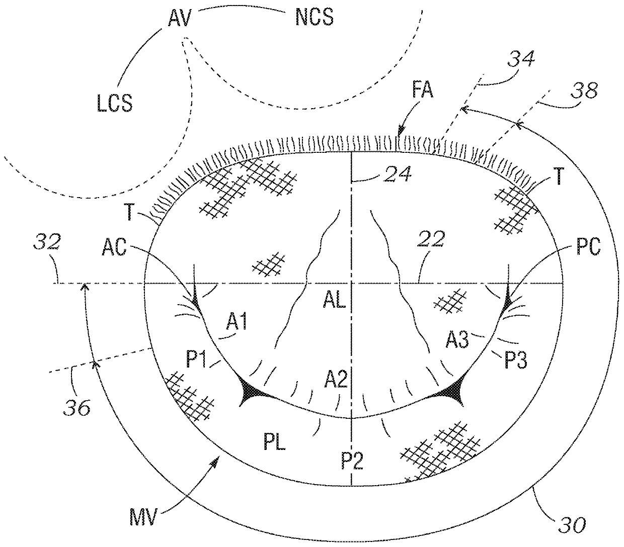
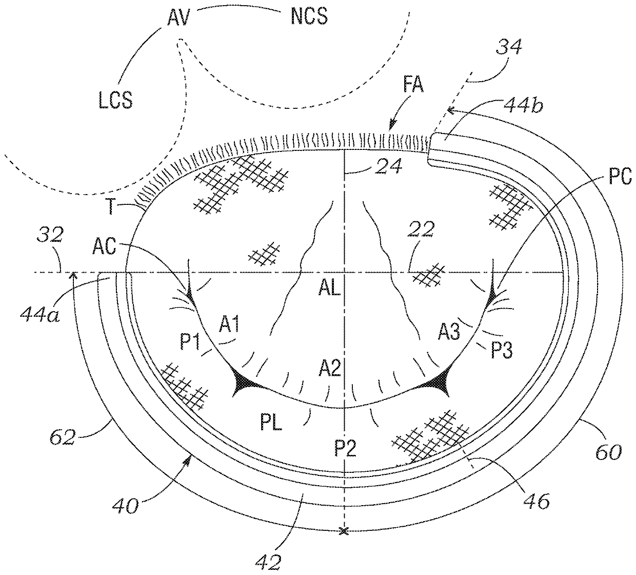
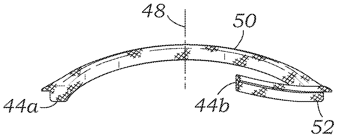
[0037] The present application discloses an asymmetric mitral annuloplasty belt, which avoids the adjacent aortic valve structure and better prevents the splitting of the mitral valve annulus along the muscle. Since the implant is a discontinuous ring, the term "band" is used here, although in some cases such implants are also referred to as "ring". In fact, the bands disclosed herein define the shape surrounding most of the mitral valve annulus, thus tracking most of the loop. A complete loop can be constructed, and in fact the shape of the band can be defined by imagining a shape extending between and connecting the free ends. For example, the preferred plan view shape of the belt of the present disclosure is a kidney shape or a D shape to conform to the peripheral shape of the usual mitral valve annulus. Therefore, "belt" and "loop" are synonymous, but the belt or loop of the present disclosure is discontinuous and thus has two free ends.

[0038] The term "axis" in referenc...


PUM


Abstract

The invention relates to an annuloplasty band and method of implantation. The band is shaped and sized to avoid the adjacent aortic valve structure and better protects against dehiscence along the muscular mitral annulus. The band is asymmetric and when implanted spans more around the side of the mitral annulus having the posterior commissure than the side with the anterior commissure. The band has a saddle shape with a posterior upward bow centered on a minor axis of the mitral annulus, and a span extending clockwise therefrom is longer than a span extending counter-clockwise. The longer spanmay be about 150 degrees while the shorter span extends about 90 degrees. A set of rings may have different saddle profiles and different plan view shapes for different sized bands. A method includesimplanting so that the band extends over the posterior leaflet and a short distance past the posterior commissure outside of the anterior leaflet.

Description

[0001] This application is a divisional application. The filing date of the original application is June 9, 2016, the application number is 201680033195.7, and the title of the invention is "Asymmetric Mitral Annuloplasty Belt". [0002] This application claims the rights and interests of US Patent Application No. 62 / 173,294 filed on June 9, 2015, the entire content of which is expressly incorporated herein. Technical field [0003] The present disclosure relates generally to annuloplasty belts, and specifically to mitral annuloplasty belts. Background technique [0004] In vertebrates, the heart is a hollow muscular organ with four pumping chambers: the left and right atrium and the left and right ventricles, each equipped with its own one-way valve. The natural heart valves are identified as aortic, mitral, tricuspid, and pulmonary (valves), and are each installed in annulus (annulus), which includes directly or indirectly attached to the atrium And dense ring of ventricular musc...

Claims


Application Information

Patent Timeline
Patent Type & Authority Applications(China)
IPC IPC(8): A61F2/24
CPCA61F2/2448A61F2/2445A61F2230/0015A61F2230/0034A61F2/2442A61F2230/0095A61F2/24
Inventor D·H·亚当斯
Owner EDWARDS LIFESCIENCES LLC
Why Eureka
Try Eureka