Medical System for Annuloplasty

a technology of medical system and annuloplasty, which is applied in the field of annuloplasty devices for treating defective mitral valves, can solve the problems of valve leakage, implanted ring, and several disadvantageous effects, and achieve less traumatic effects on the anatomy, less complex procedure, and less patient risk.

Pending Publication Date: 2022-11-03
MEDTENTIA INT LTD OY
View PDF5 Cites 0 Cited by
  • Summary
  • Abstract
  • Description
  • Claims
  • Application Information

AI Technical Summary

Benefits of technology

[0004]The above problems may have dire consequences for the patient and the health care system. Patient risk is increased.
[0005]Hence, an improved annuloplasty device for performing downsizing and reshaping of the valve annulus would be advantageous and in particular allowing for ensuring long-term functioning, less complex procedure, and less traumatic effects on the anatomy and increased patient safety. Also, a method of downsizing and reshaping the mitral valve annulus with such medical annuloplasty device would be advantageous.
[0006]Accordingly, examples of the present invention preferably seek to mitigate, alleviate or eliminate one or more deficiencies, disadvantages or issues in the art, such as the above-identified, singly or in any combination by providing a device according to the appended patent claims.
[0007]According to a first aspect an annuloplasty device is provided for treating a defective mitral valve having an annulus, comprising a removable and flexible elongate displacement unit for temporary insertion into a coronary sinus (CS) adjacent the valve, wherein the displacement unit has a delivery state for delivery into the CS, and an activated state to which the displacement unit is temporarily and reversibly transferable from said delivery state, the displacement unit comprises a proximal reversibly expandable portion, a distal anchoring portion being movable in relation to the proximal expandable portion in a longitudinal direction of the displacement unit to said activated state in which the shape of the annulus is modified to a modified shape, wherein the proximal expandable portion is reversibly foldable to an expanded state for positioning against a tissue wall at the entrance of the CS, and wherein the elongate displacement unit comprises a lumen extending in the longitudinal direction and having a distal opening arranged distally of the distal anchoring portion, and at least one proximal opening arranged between the distal anchoring portion and the proximal expandable portion.
[0008]According to a second aspect medical system for treating a defective mitral valve having an annulus is provided. The system comprises in combination; an annuloplasty device for treating a defective mitral valve having an annulus, comprising a removable and flexible elongate displacement unit for temporary insertion into a coronary sinus (CS) adjacent the valve, wherein the displacement unit has a delivery state for delivery into the CS, and an activated state to which the displacement unit is temporarily and reversibly transferable from said delivery state, the displacement unit c...

Problems solved by technology

The mitral and tricuspid valve leaflets or supporting chordae may degenerate and weaken or the annulus may dilate leading to valve leak.
Permanent implants have several disadvantageous effects, for example since they are implanted into the CS which is a source for later complications.
Thus, a problem with the prior art implants in the CS is that such implants may be less effective in retaining the desired geometry of the annulus.
This pose significant requirements on the long-term function of the implant, that may not be as effective as annuloplasty rings to start with.
A further problem with prior art ...

Method used


Image

  • Medical System for Annuloplasty
  • Medical System for Annuloplasty
  • Medical System for Annuloplasty

Examples


Embodiment Construction

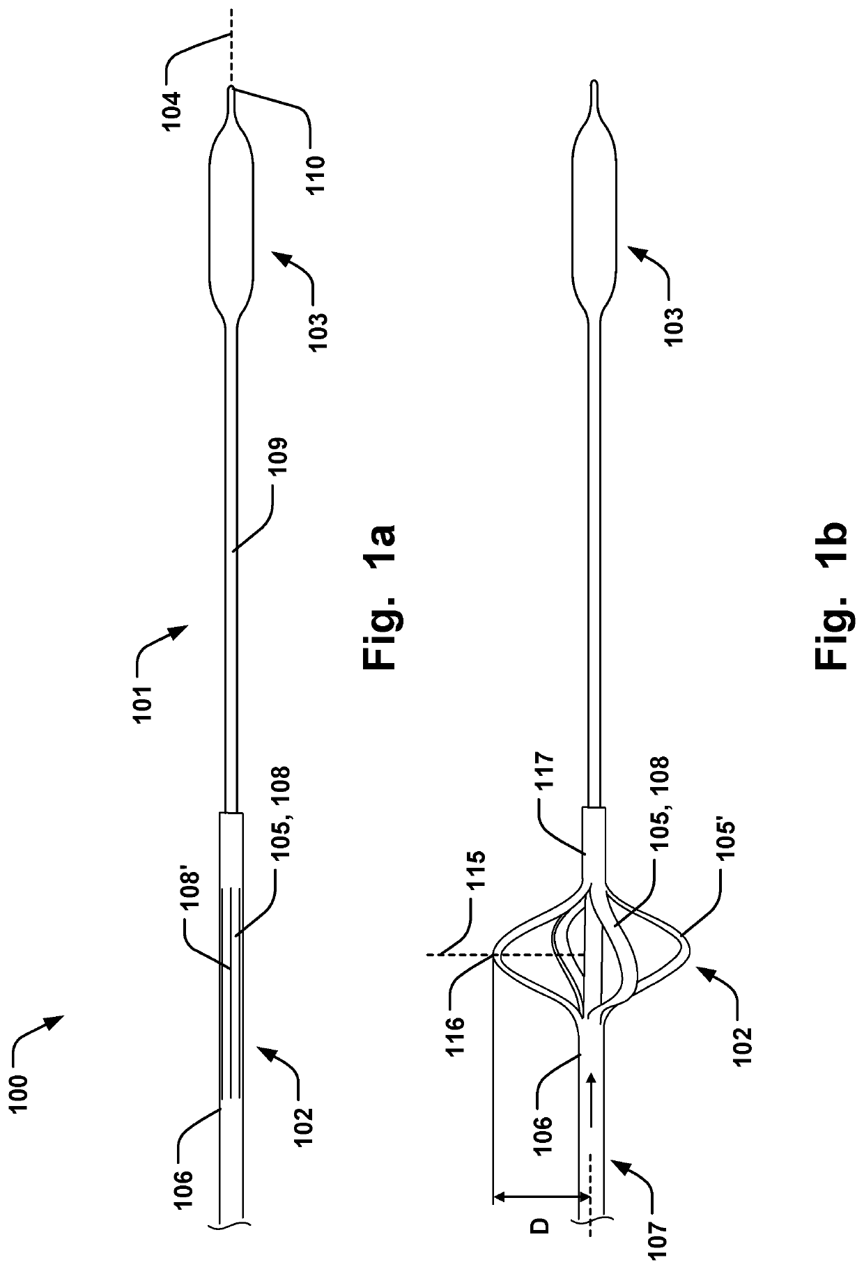
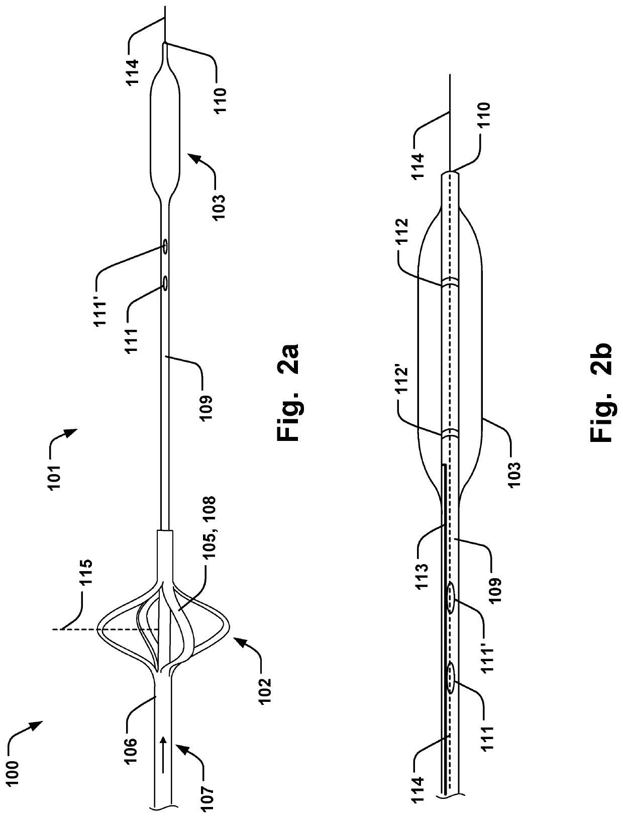
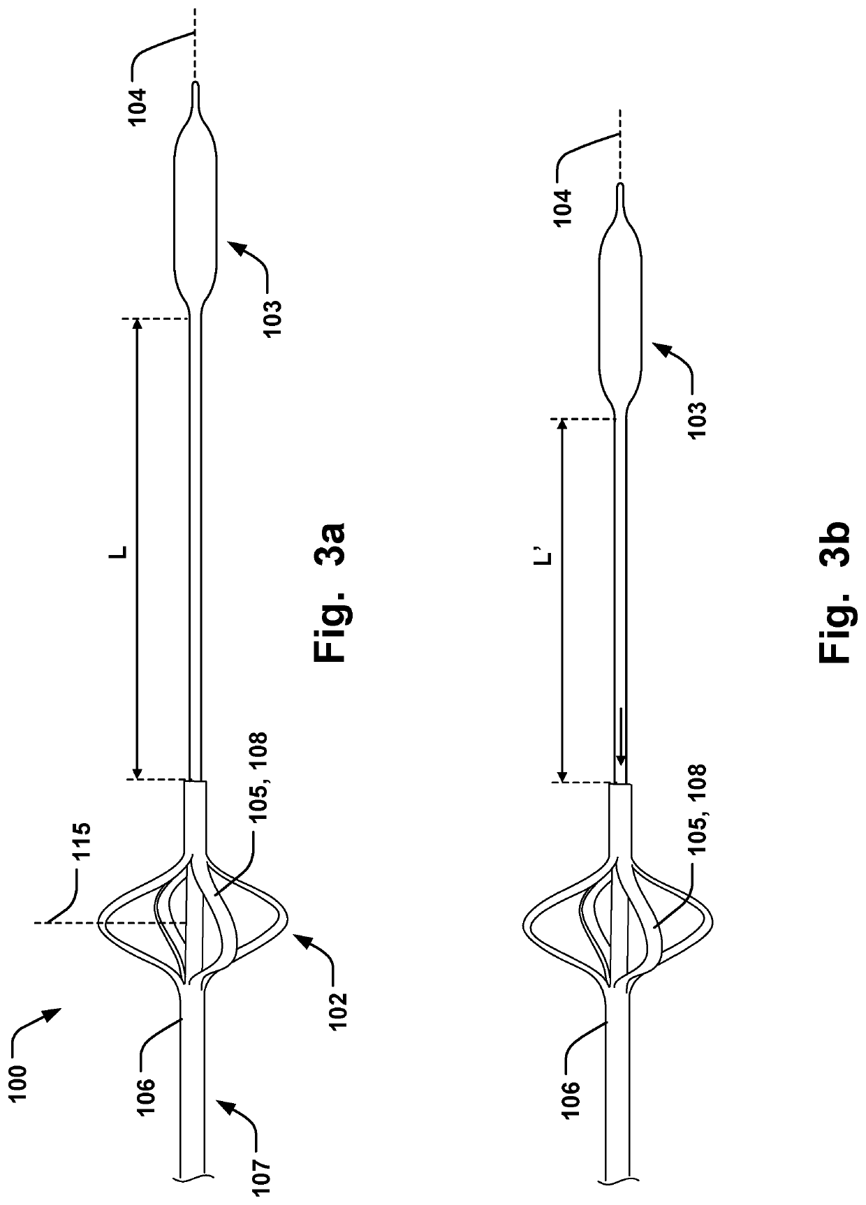
[0033]Specific embodiments of the invention will now be described with reference to the accompanying drawings. This invention may, however, be embodied in many different forms and should not be construed as limited to the embodiments set forth herein; rather, these embodiments are provided so that this disclosure will be thorough and complete, and will fully convey the scope of the invention to those skilled in the art. The terminology used in the detailed description of the embodiments illustrated in the accompanying drawings is not intended to be limiting of the invention. In the drawings, like numbers refer to like elements.

[0034]The following description focuses on an embodiment of the present invention applicable to cardiac valve implants such as annuloplasty rings. However, it will be appreciated that the invention is not limited to this application but may be applied to many other annuloplasty implants and cardiac valve implants including for example replacement valves, and o...


PUM


Abstract

An annuloplasty device is disclosed for treating a defective mitral valve having an annulus, comprising a removable and flexible elongate displacement unit for temporary insertion into a coronary sinus (CS) adjacent the valve, wherein the displacement unit has a delivery state for delivery into the CS, and an activated state to which the displacement unit is temporarily and reversibly transferable from said delivery state, the displacement unit comprises a proximal reversibly expandable portion, a distal anchoring portion being movable in relation to the proximal expandable portion in a longitudinal direction of the displacement unit to said activated state in which the shape of the annulus is modified to a modified shape, wherein the proximal expandable portion is reversibly foldable to an expanded state for positioning against a tissue wall at the entrance of the CS.

Description

FIELD OF THE INVENTION[0001]This invention pertains in general to the field of annuloplasty devices for treating a defective mitral valve. More particularly the invention relates to a medical system of devices for treating a defective mitral valve via coronary sinus and an annuloplasty implant for fixation of the annulus, and a method therefore.BACKGROUND OF THE INVENTION[0002]Diseased mitral and tricuspid valves frequently need replacement or repair. The mitral and tricuspid valve leaflets or supporting chordae may degenerate and weaken or the annulus may dilate leading to valve leak. Mitral and tricuspid valve replacement and repair are frequently performed with aid of an annuloplasty ring, used to reduce the diameter of the annulus, or modify the geometry of the annulus in any other way, or aid as a generally supporting structure during the valve replacement or repair procedure.[0003]Implants have previously been introduced into the coronary sinus (CS) in order to affect the shap...

Claims


Application Information

Patent Timeline
IPC IPC(8): A61F2/24
CPCA61F2/2451A61F2/2466A61F2230/0091A61F2250/0003A61F2250/0098A61F2250/001A61F2220/0008A61F2250/0039A61F2/2442A61F2/2427
Inventor KERÄNEN, OLLIVALLIKARI, JOUKOZERKOWSKI, HANS-REINHARD
Owner MEDTENTIA INT LTD OY
Why Eureka
Try Eureka