Orthopedic treatment table

A treatment table and orthopaedic technology, applied in the medical field, can solve the problems of not taking up much space, unable to meet the use requirements of different treatment scenarios, unable to meet the use requirements, etc., to achieve the effect of convenient operation and convenient switching

Active Publication Date: 2020-08-14
义乌市宏博机械科技有限公司
View PDF5 Cites 2 Cited by
  • Summary
  • Abstract
  • Description
  • Claims
  • Application Information

AI Technical Summary

Problems solved by technology

[0002] Treatment tables are frequently used in orthopedics, but the existing treatment tables are basically fixed, that is, the size of the operation surface of the treatment table is fixed, which cannot meet the needs of different treatment scenarios. If the operation surface is too small, it cannot meet the nee

Method used


Image

  • Orthopedic treatment table
  • Orthopedic treatment table
  • Orthopedic treatment table

Examples


Example Embodiment

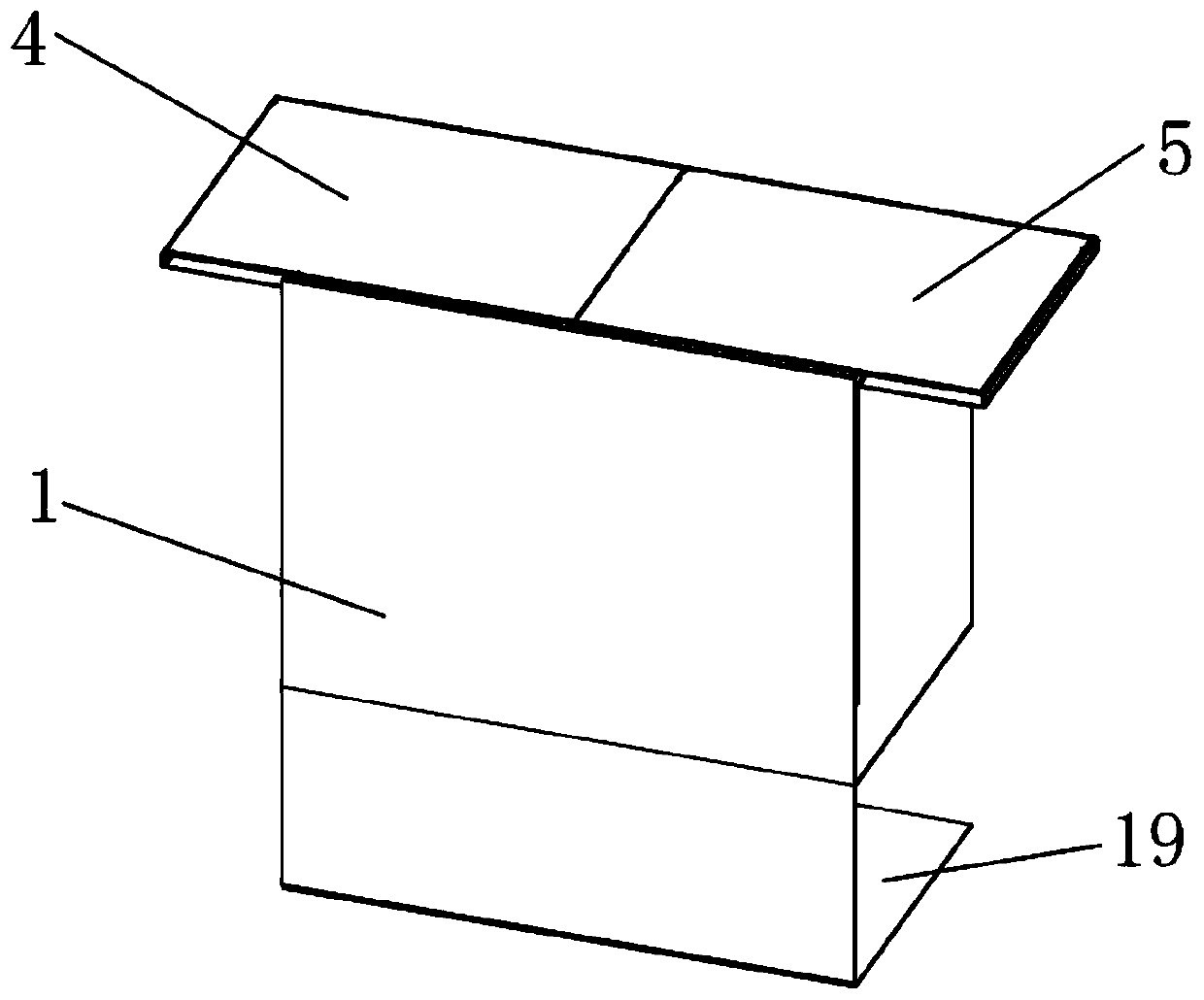
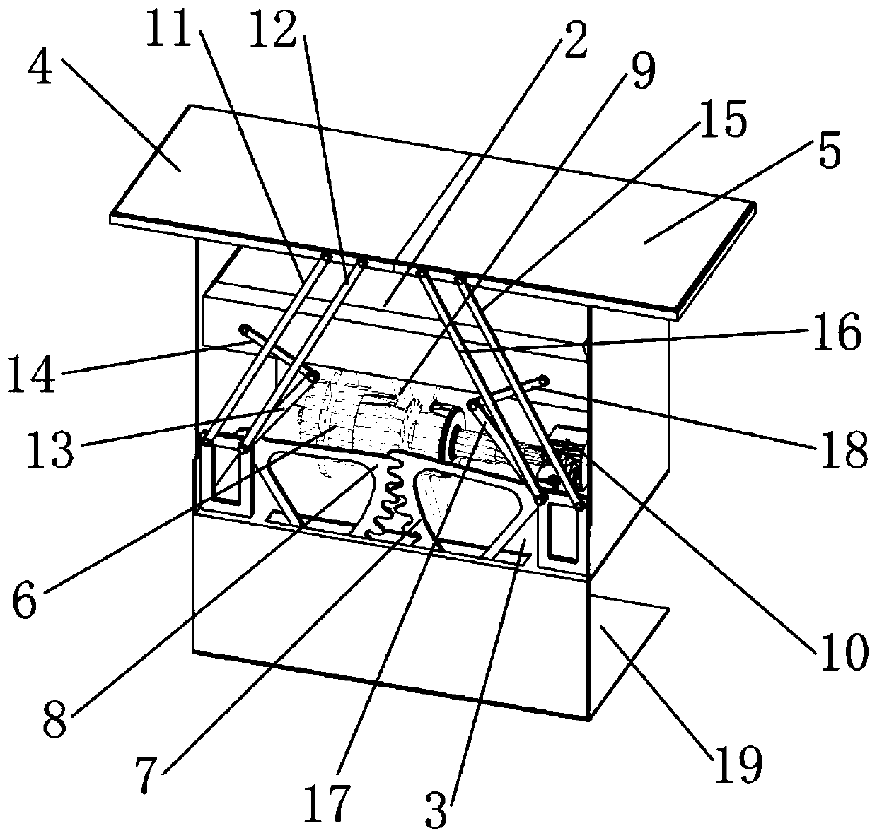
[0023] Embodiment one: refer to Figure 1 to Figure 4 As shown, an orthopedic treatment table in this embodiment includes a box body 1 and a workbench 2. A cavity 3 is provided in the box body 1, and the top of the cavity body 3 is open. The workbench 2 is slidably fitted in the cavity body 3 and It can move up and down along the cavity 3. The left and right display panels 4 and 5 are slidably connected to the left and right sides of the top of the box body 1. The cavity 3 is equipped with a motor 6, a driving gear 7 and a driven gear 8. The driving gear 7 is composed of The motor 6 is driven to rotate between the first position and the second position, the driven gear 8 is meshed with the driving gear 7, the left end of the left exhibition board 4 and the workbench 2 are connected with the driven gear 8 through the left connecting rod assembly, the right exhibition board 5 and The right end of the workbench 2 is connected to the drive gear 7 through the right connecting rod a...

Example Embodiment

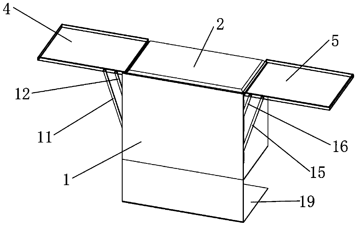
[0027] Embodiment two: if Figure 5As shown, the right end of the right display board 5 in this embodiment is connected with an extension board 20, and the extension board 20 is connected above the right display board 5 through a latch 21, and the right end of the right display board 5 and the extension board 20 are provided with a plug for the latch 21 to pass through. The top of the latch 21 is provided with an annular screw part 22, which defines an annular space 23, the external thread of the latch 21 is connected with a lock button 24, and the inside of the latch 21 is provided with a push rod cavity, and the push rod cavity It communicates with the annular space 23, and a push rod 25 is arranged in the push rod cavity, and the top of the push rod 25 stretches out of the push rod cavity and then extends into the annular space 23, and both sides of the lower part of the latch 21 are provided with lock grooves 26, and the bottom of the lock groove 26 is in contact with the p...


PUM


Abstract

The invention discloses an orthopedic treatment table. The orthopedic treatment table comprises a box body and a workbench, wherein a cavity is formed in the box body; the workbench is slidably connected in the cavity in a matched mode; a left display board and a right display board are slidably connected to the left side and the right side of the top of the box body in a matched mode; a motor, adriving gear and a driven gear are arranged in the cavity; the driving gear is driven by the motor to rotate between a first position and a second position; the left display board and the left end ofthe workbench are connected with the driven gear through a left connecting rod assembly; the right display board and the right end of the workbench are connected with the driving gear through a rightconnecting rod assembly; when the driving gear is located at the first position, the workbench is located at the bottom of the cavity, the left display board and the right display board are in butt joint to form a box cover covering an opening of the cavity, and a storage cavity used for containing articles is formed between the box cover and the workbench; and when the driving gear is located atthe second position, the workbench is located at the top of the cavity, and the left display board and the right display board are located on the two sides of the workbench respectively. In the abovementioned way, the treatment table can be switched between a small operation surface and a large operation surface, switching is quite convenient, and operation is facilitated.

Description

technical field [0001] The invention relates to the field of medical technology, in particular to an orthopedic treatment table. Background technique [0002] Treatment tables are frequently used in orthopedics, but the existing treatment tables are basically fixed, that is, the size of the operation surface of the treatment table is fixed, which cannot meet the needs of different treatment scenarios. If the operation surface is too small, it cannot meet the needs of use. If the operation surface is too large, it will not take up much space, and there will be great disadvantages. Therefore, it is necessary to optimize the structure of the existing fixed treatment table so that the size of the operation surface can be adjusted to suit different treatment scenarios. need. Contents of the invention [0003] The technical problem to be solved by the present invention is to provide an orthopedic treatment table, which can solve the problem that the size of the operating surfac...

Claims


Application Information

Patent Timeline
IPC IPC(8): A61G13/02A61G13/04A61G13/10A61B50/31A61B50/24
CPCA61G13/02A61G13/04A61G13/10A61B50/31A61B50/24A61G2210/10A61B2050/311A61B2050/0059
Inventor 李霞
Owner 义乌市宏博机械科技有限公司
Why Eureka
Try Eureka