
Power equipment transportation device

A technology for transportation devices and power equipment, applied in transportation and packaging, switchgear, electrical components, etc., can solve problems such as inability to stop at any time, affect work efficiency, and stability of power equipment, so as to reduce burden and protect safety Effect

Inactive Publication Date: 2020-08-14
华清八度光电集团有限公司
View PDF0 Cites 0 Cited by
  • Summary
  • Abstract
  • Description
  • Claims
  • Application Information

AI Technical Summary

Problems solved by technology

[0002] In the installation of electric equipment, many large-scale electric equipment will be involved. The transportation equipment is the carrier for transporting goods from one place to another area, and it is a means of transportation. At present, in the new community projects, most of the power distribution rooms are designed in underground garages. Most of the power distribution rooms have no special passages, the terrain is complex, and transport vehicles cannot enter. When installing the power facilities in the power distribution room, it needs to be carried by manpower or with the help of certain transportation facilities; but the existing power equipment transportation device is in During the transportation process, the power equipment cannot maintain a certain stability in the transportation device, and it is easy to damage the power equipment, and the existing power equipment transportation device cannot stop at any time during the transportation process, which increases the burden on the transportation workers. Affect work efficiency

Method used


Image

  • Power equipment transportation device
  • Power equipment transportation device
  • Power equipment transportation device

Examples


Embodiment Construction

[0018] The following will clearly and completely describe the technical solutions in the embodiments of the present invention with reference to the accompanying drawings in the embodiments of the present invention. Obviously, the described embodiments are only some, not all, embodiments of the present invention. Based on the embodiments of the present invention, all other embodiments obtained by persons of ordinary skill in the art without making creative efforts belong to the protection scope of the present invention.

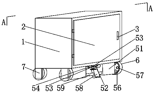
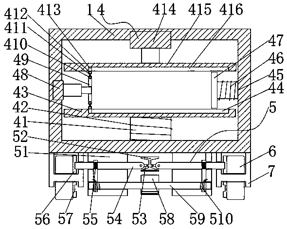
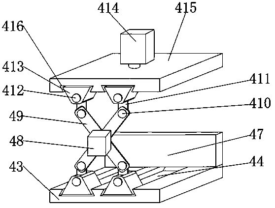
[0019] see Figure 1-3, the present invention provides a technical solution: a power equipment transportation device, including a box body 1, a box door 2, a handle 3, a stabilizing component 4, a moving component 5, a tire 6 and a tire connecting plate 7, one side of the box body 1 A stabilizing assembly 4 is installed on the inner wall; the stabilizing assembly 4 includes a first telescopic rod 41, a first spring 42, a first limiting plate 43, a first limiti...


PUM


Abstract

The invention discloses a power equipment transportation device. The device comprises a box body, a box door, a handle, a stabilizing assembly, a moving assembly, tires and tire connecting plates. Thestabilizing assembly is installed on an inner wall of one side of the box body, a first telescopic rod is fixedly installed on the inner wall of one side of the box body, an outer wall of one side ofthe first telescopic rod is connected with a first spring, and a first limiting plate is fixedly welded to the outer wall of one end of the first telescopic rod. According to the power equipment transportation device, the stabilizing assembly and the moving assembly are adopted, and a first hydraulic cylinder, a second hydraulic cylinder, a first limiting plate and a second limiting plate in thestabilizing assembly are matched so that power equipment is kept in a stable state in a transportation process, and the safety of the power equipment is protected; and the tires, a limiting pedal, a brake pedal, a limiting hole, a fourth connecting shaft and a third spring in the moving assembly are matched, more time and labor are saved in the transportation process of the transportation device,the transportation device can be stopped at any time, and burden of workers is relieved.

Description

technical field [0001] The invention relates to the technical field of electric equipment, in particular to an electric equipment transportation device. Background technique [0002] In the installation of electric equipment, many large-scale electric equipment will be involved. The transportation equipment is the carrier for transporting goods from one place to another area, and it is a means of transportation. At present, in the new community projects, most of the power distribution rooms are designed in underground garages. Most of the power distribution rooms have no special passages, the terrain is complex, and transport vehicles cannot enter. When installing the power facilities in the power distribution room, it needs to be carried by manpower or with the help of certain transportation facilities; but the existing power equipment transportation device is in During the transportation process, the power equipment cannot maintain a certain stability in the transportation...

Claims


Application Information

Patent Timeline
Patent Type & Authority Applications(China)
IPC IPC(8): B62B3/00B62B3/04B62B5/04B62B5/00H02B3/00
CPCB62B3/005B62B3/04B62B5/00B62B5/04B62B2202/00B62B2203/60H02B3/00
Inventor 刘一锋
Owner 华清八度光电集团有限公司
Learn More