Constant-tension pay-off device

A wire pay-off device and constant tension technology, applied in the field of railway guide erection, can solve the problems of reducing the quality of the bearing wire, affecting the quality of the bearing wire, complex structure of the bracket, etc., and achieving simple and convenient installation and disassembly, high degree of automation, and stable tension. Effect

Pending Publication Date: 2020-08-14
CHINA CREC RAILWAY ELECTRIFICATION BUREAU GRP
View PDF0 Cites 4 Cited by
  • Summary
  • Abstract
  • Description
  • Claims
  • Application Information

AI Technical Summary

Problems solved by technology

[0003] The pay-off frame in the prior art is only a bracket fixed on the car body, and a winding device is fixed on the bracket, and the carrying wire comes out of the winding device and is erected on the pole column of the catenary after passing through the tension applying device. The winding device is wider, and the two edges have a certain distance. When the wire is unwound, the supporting wires at the two edges of the winding device cannot be aligned with the tension applying device, so that the released supporting wire and the wire wound on the pay-off frame cannot be aligned. The friction and pulling of the carrying wire seriously affects the quality of the carrying wire
After the carrying wire in the prior art is released, it often touches the ground and the rail due to insufficient tension. After a long period of contact, the carrying wire will be severely worn, the quality of the carrying wire will be reduced, and a safety hazard will be caused.
At the same time, the structure of the support in the prior art is complex, and when installing the winding device, the entire support needs to be disassembled and installed, which is time-consuming and laborious, and the production cost is relatively high

Method used


Image

  • Constant-tension pay-off device
  • Constant-tension pay-off device
  • Constant-tension pay-off device

Examples


Embodiment

[0034] Example Constant tension pay-off device

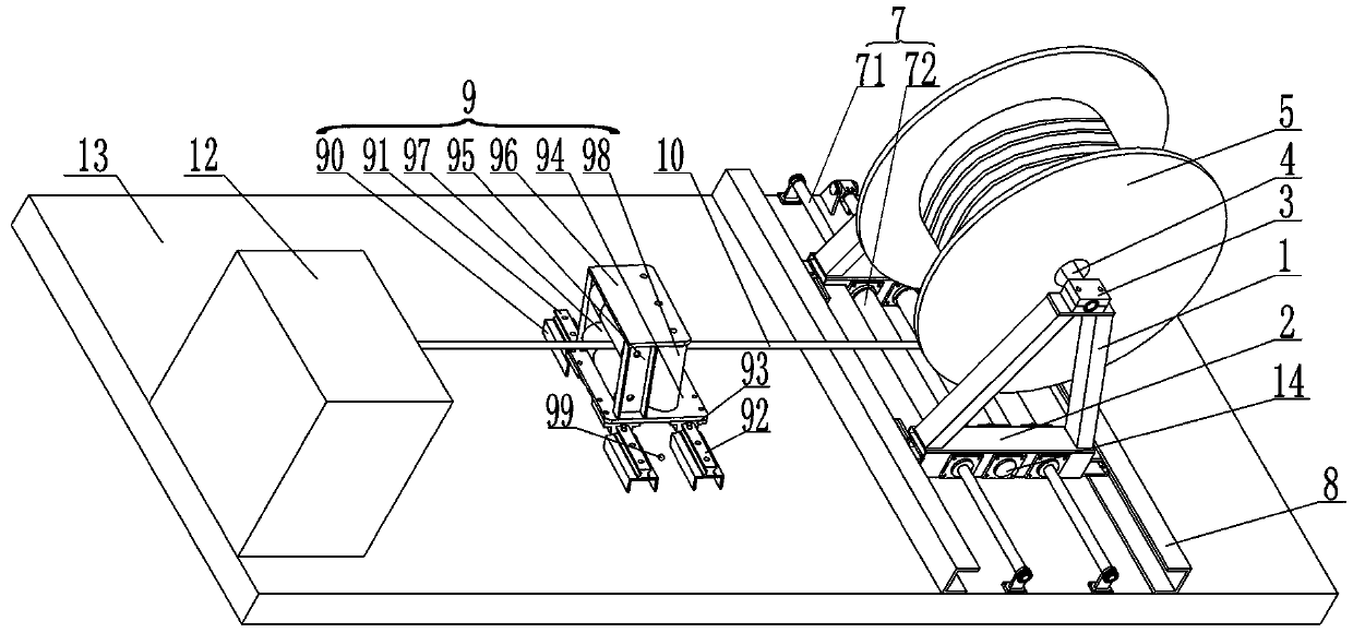
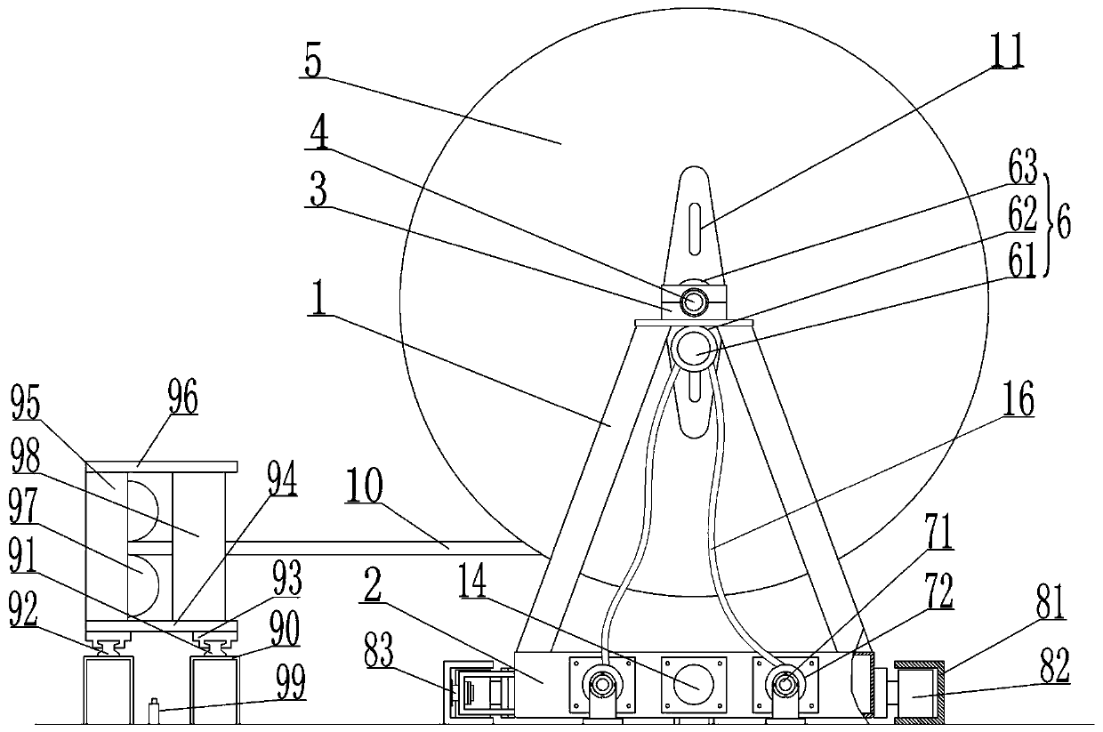
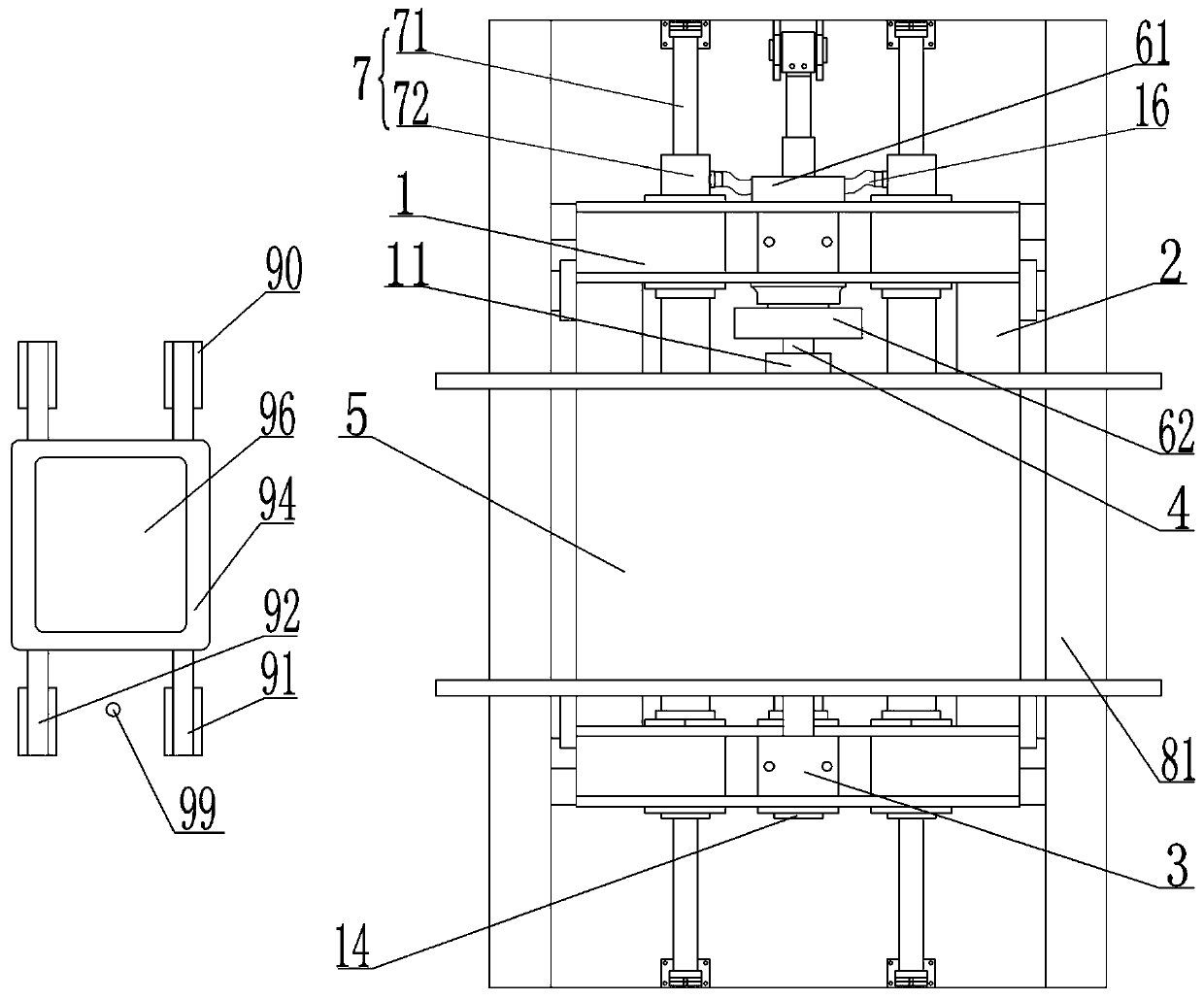
[0035] This example Figure 1-Figure 5 As shown, a constant tension pay-off device includes a support 1, a rotating shaft 4 rotatably connected to the support 1, a winding device 5 fixed on the rotating shaft 4 for winding the bearing wire 10, and the support 1 is two The trapezoidal structures arranged in parallel are formed, the upper part is narrow and the lower part is wider, and the lower parts are connected together by the welded base 2 . The top of the bracket 1 is detachably provided with two bearing seats 3, the bearing seats 3 are respectively arranged on two parallel trapezoidal structures of the bracket 1, and the rotating shaft 4 is connected to the bearing seats 3 through bearing rotation, The two ends of the rotating shaft 4 are respectively arranged on the two bearing seats 3 . The bearing seat 3 is composed of upper and lower parts, which are fastened to each other on the rotating shaft 4, and the two parts ar...


PUM


Abstract

The invention discloses a constant-tension pay-off device and belongs to the technical field of railway bearing conductor erection. The constant-tension pay-off device comprises a support, a rotary shaft rotationally connected to the support, and a winding device which is fixedly arranged on the rotary shaft and used for winding a bearing conductor. The support is connected to a car body, used forbearing the support, in a sliding mode through sliding rail devices. Moving devices and driving devices are fixedly arranged on the support, the moving devices enable the support to move along the sliding rail devices, the driving devices are used for driving the rotary shaft to rotate and provide tension for the winding device, and the force application direction of the driving devices is opposite to the pay-off direction of the winding device. The constant-tension pay-off device further comprises a guide device used for detecting the position of the bearing conductor and providing an actuating signal for the moving devices, and a control device. The constant-tension pay-off device provided by the invention is high in automation degree can be automatically aligned with a tension application device during paying-off, the tension is constant and can be automatically adjusted, friction between the bearing conductor and the ground and dragging are reduced during paying-off, the service life is long, dismounting and mounting are convenient, guiding is stable, and the device is applicable to all pay-off devices.

Description

technical field [0001] The invention belongs to the technical field of railway bearing and erection, and relates to a wire-releasing device, in particular to a constant-tension wire-releasing device. Background technique [0002] During the construction or maintenance of electrified railways, the tension of the catenary wires plays an extremely important role in maintaining the spatial form of the catenary. The carrying wire is a special form of contact wire or catenary cable erected above the railway line to supply power to electric locomotives. During construction, the carrying wire needs to be erected on the wrist arm of the catenary pole and maintain a certain tension. Since the carrying wire needs to be wound on the pay-off rack before being erected, the carrying wire will become bent and produce radians, and the existence of the carrying wire's own radian will cause intermittent ripples, forming arc discharge, which will damage the power supply. The locomotive caused ...

Claims


Application Information

Patent Timeline
Patent Type & Authority Applications(China)
IPC IPC(8): B65H59/38B65H49/30B65H49/38B65H59/04B65H63/00B65H59/40B65H57/28B60M1/22B60M1/28
CPCB60M1/22B60M1/28B65H49/30B65H49/38B65H57/28B65H59/04B65H59/381B65H59/40B65H63/00B65H2701/35
Inventor 刘桐任增堂苗俊波袁英杰陈桀李剑锋张柏滔唐立新高越崔达周辰彦
Owner CHINA CREC RAILWAY ELECTRIFICATION BUREAU GRP
Why Eureka
Try Eureka