Supercharge Your Innovation With Domain-Expert AI Agents!

Movable shaft head assembly

A technology of movable shafts and components, applied in the direction of shafts and bearings, can solve problems such as eccentric movement, achieve the effect of ensuring neutrality and improving product quality

Pending Publication Date: 2020-08-14
张家港市瑞昌智能机器系统有限公司
View PDF0 Cites 0 Cited by
  • Summary
  • Abstract
  • Description
  • Claims
  • Application Information

AI Technical Summary

Problems solved by technology

[0003] In order to solve the problem of eccentric movement after clamping the top of the I-shaped wheel after long-term use and grinding of the inner hole, the invention provides a movable shaft head assembly to solve this problem

Method used


Image

  • Movable shaft head assembly
  • Movable shaft head assembly
  • Movable shaft head assembly

Examples


Embodiment Construction

[0018] The following will clearly and completely describe the technical solutions in the embodiments of the present invention with reference to the accompanying drawings in the embodiments of the present invention. Obviously, the described embodiments are only some, not all, embodiments of the present invention. Based on the embodiments of the present invention, all other embodiments obtained by persons of ordinary skill in the art without creative efforts fall within the protection scope of the present invention.

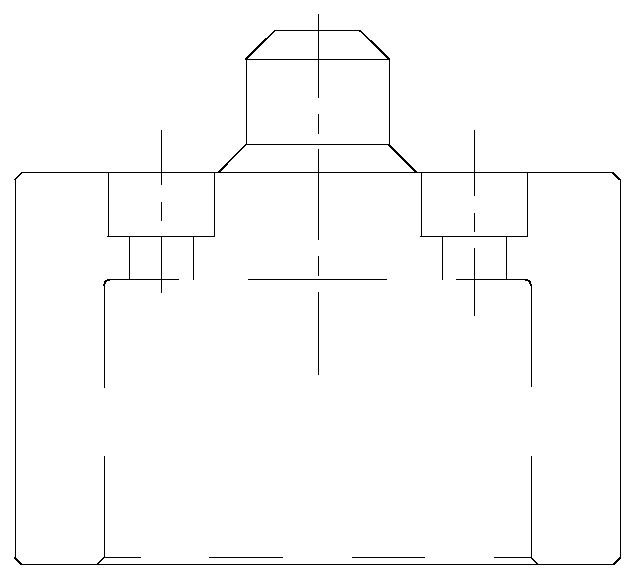
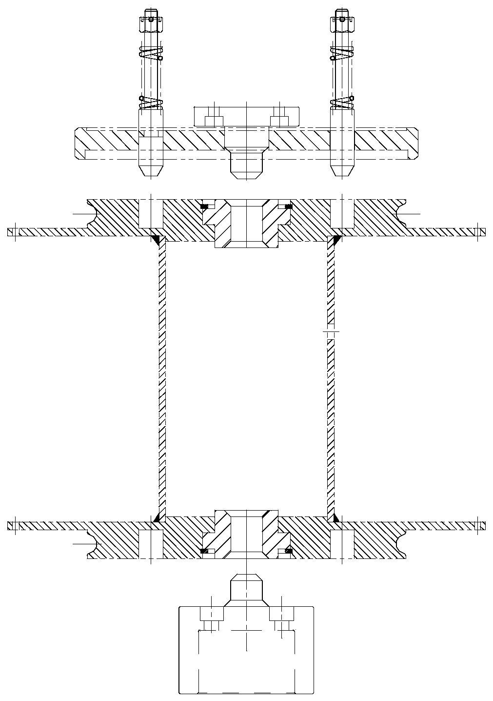
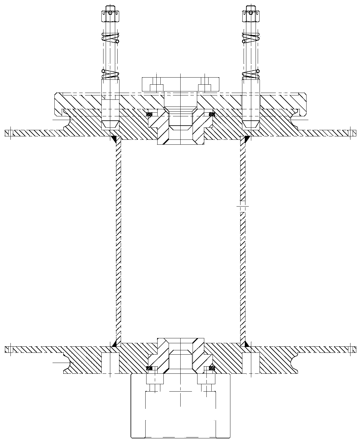
[0019] Such as Figure 4-6 As shown, the movable shaft head assembly of the present invention includes a movable pressure sleeve 1 and a movable shaft head arranged in the movable pressure sleeve 1, and the movable shaft head includes a shaft head top 2 fixedly connected from top to bottom, a shaft head middle part 3 and a shaft The lower part of the head 4, the top of the movable pressure sleeve 1 has a through hole 5, the top of the shaft head 2 includes a first ...


PUM


Abstract

The invention discloses a movable shaft head assembly. The movable shaft head assembly comprises a movable pressing sleeve and a movable shaft head, wherein the movable shaft head comprises a shaft head top part, a shaft head middle part and a shaft head lower part which are fixedly connected from top to bottom, a through hole is formed in the top of the movable pressing sleeve, the shaft head toppart comprises a first cylinder part, a frustum part and a second cylinder part which are fixedly connected from top to bottom, the first cylinder part, the frustum part and the second cylinder partare concentrically arranged, the bottom surface area of the second cylinder part is larger than that of the first cylinder part, the diameter of the upper surface of the frustum part is the same as that of the bottom surface of the first cylinder part, the diameter of the lower surface of the frustum part is the same as that of the bottom surface of the second cylinder part, the first cylinder part stretched out of the through hole, a compression spring set is arranged between the shaft head middle part and the inner side of the top of the movable pressing sleeve, an elastic check ring for a hole is arranged at the bottom of the movable pressing sleeve, and the lower part of the shaft head extends out of the elastic check ring for the hole. According to the movable shaft head assembly, theproblem of eccentricity of a spool after long-term use and large-bore grinding and opposite-jacking clamping is effectively solved.

Description

technical field [0001] The invention relates to a shaft head assembly, in particular to a movable shaft head assembly. Background technique [0002] In the past, we used cylindrical shaft heads, such as Figure 1-3 , the size and shape of the cylindrical shaft head cannot be changed, but in the actual production process, we found that when the inner hole of the I-shaped wheel is worn for a long time, after the I-shaped wheel is clamped to the top, it will be eccentric and move, so that the When rotating, if it is unbalanced, there will be too much shaking, which will affect the quality of the product. So the engineer directly changed the cylindrical shaft head into a conical shaft head, but during the jacking process, the tapered shaft head is in line contact with the inner hole of the I-shaped wheel, and other surfaces are not in contact, so that during the jacking process , the I-shaped wheel will be tilted, and it is impossible to perform accurate top clamping work. Co...

Claims


Application Information

Patent Timeline
Patent Type & Authority Applications(China)
IPC IPC(8): F16C13/00
CPCF16C13/00
Inventor 王富礼史修进王波
Owner 张家港市瑞昌智能机器系统有限公司
Features
  • R&D
  • Intellectual Property
  • Life Sciences
  • Materials
  • Tech Scout
  • Unparalleled Data Quality
  • Higher Quality Content
  • 60% Fewer Hallucinations
Learn More