
Marangoni drying device with adjustable injection angle

A drying device and spray angle technology, applied in the direction of drying gas arrangement, non-progressive dryer, drying, etc., can solve the problems of high-speed backsplash, large equipment volume, large space occupation and difficult composite integration, etc., to reduce equipment The effect of operating speed, improving equipment stability, and saving valuable space

Active Publication Date: 2020-08-14
TSINGHUA UNIV +1
View PDF7 Cites 3 Cited by
  • Summary
  • Abstract
  • Description
  • Claims
  • Application Information

AI Technical Summary

Problems solved by technology

[0005] However, the common problems of SRD and Marangoni drying in the prior art include large equipment volume, complex structure, high-speed backsplash, etc.; for example, the chamber of the Marangoni drying equipment of US Patent No. The body needs to be composed of a vertical receiving part and an inclined pulling part, so it takes up a lot of space and is difficult to combine and integrate; for SRD, it needs horizontal high-speed rotation to provide a large centrifugal force to drive off the liquid on the wafer surface, and the over High speed may cause a series of problems such as backsplash
It should be pointed out that although there is a horizontal Marangoni drying technology, since the wafer is generally transported vertically in the CMP equipment, the wafer is turned from a vertical state to a horizontal state before cleaning and drying. And flipping the wafer from a horizontal state to a vertical state after cleaning and drying will not only affect the efficiency of wafer transfer operations, but may also cause a series of problems such as wafer damage

Method used


Image

  • Marangoni drying device with adjustable injection angle
  • Marangoni drying device with adjustable injection angle
  • Marangoni drying device with adjustable injection angle

Examples


Embodiment Construction

[0027] The present application will be further described in detail below with reference to the accompanying drawings and embodiments. It should be understood that the specific embodiments described here are only used to explain related invention points, rather than to limit the invention. It should also be noted that, for ease of description, only parts related to the invention are shown in the drawings.

[0028] It should be noted that, in the case of no conflict, the embodiments in the present application and the features in the embodiments can be combined with each other. In addition, it should also be noted that the terms such as front, back, up, down, left, right, top, bottom, front, back, horizontal, vertical, etc. used in this application to indicate orientation are only for convenience of description and are used to to aid in the understanding of relative positions or orientations, and is not intended to limit the orientation of any device or structure.

[0029] The ...


PUM


Abstract

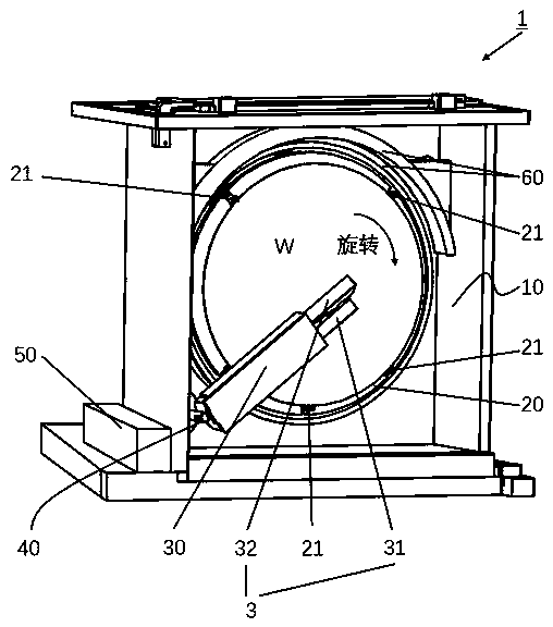
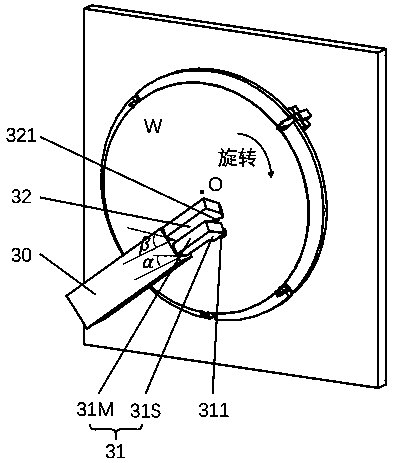
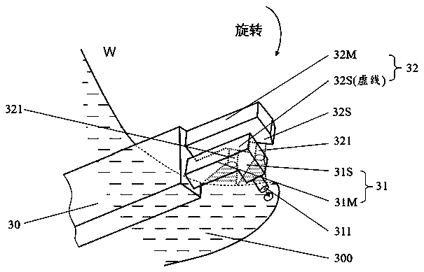
The invention provides a Marangoni drying device with an adjustable injection angle. The device comprises a driving mechanism for vertically rotating a wafer, a supply arm for conveying a fluid, and abox body, wherein the supply arm is vertically swingable and supplies the fluid onto the wafer through a nozzle assembly provided at a free end thereof; the nozzle assembly comprises a first nozzle arm with a nozzle and a second nozzle arm with nozzles, wherein the first nozzle arm and the second nozzle arm extend along the supply arm and are rotatably fixed at the free end of the supply arm, thefirst nozzle arm is positioned below the second nozzle arm, the first nozzle arm is provided with the one nozzle, the second nozzle arm is provided with the two nozzles, the nozzle of the first nozzle arm is perpendicular to the axis of the first nozzle arm, and the nozzles of the second nozzle arm are obliquely arranged on the second nozzle arm in a backwards-hooked or forwards-stretched mode.

Description

technical field [0001] The present application relates to the field of semiconductor manufacturing equipment, in particular to a Marangoni drying device with adjustable spray angle. Background technique [0002] Wafer manufacturing is a key link that restricts the development of the VLSI (chip, IC, Integrated Circuit Chip) industry. As the feature size of integrated circuits continues to shrink, the surface quality requirements of wafers are getting higher and higher, so the control of defect size and number in the wafer manufacturing process is becoming more and more stringent. In the logic chip manufacturing process, when the feature size develops from 14nm to 7nm, the control range of pollutants above 19nm is also reduced from 100 to 50, gradually approaching the limits of cleaning technology and measurement technology. Contaminants are an important factor that causes the quality of the wafer surface to deteriorate or even produce defects. Therefore, cleaning technology ...

Claims


Application Information

Patent Timeline
Patent Type & Authority Applications(China)
IPC IPC(8): F26B11/18F26B21/00H01L21/67
CPCF26B11/18F26B21/004H01L21/67034
Inventor 李长坤赵德文曹自立路新春
Owner TSINGHUA UNIV
Learn More