Mobile partial discharge remote diagnosis and detection system and partial discharge positioning method

A remote diagnosis and detection system technology, applied in signal transmission systems, measuring electronics, measuring devices, etc., can solve problems such as poor flexibility, high experience requirements for experimenters, and great influence on the technical level of testers, achieving high flexibility, High cost performance and the effect of overcoming the phenomenon of missed detection

Inactive Publication Date: 2020-08-14
JIANGSU UNIV
View PDF6 Cites 3 Cited by
  • Summary
  • Abstract
  • Description
  • Claims
  • Application Information

AI Technical Summary

Problems solved by technology

[0003] 1) In recent years, the scale of domestic cable lines has increased rapidly, and the workload of carrying out live detection is heavy. When carrying out live detection in strict accordance with the requirements of the power grid company, there is a serious shortage of instruments and test personnel
[0004] 2) The regular detection method of the portable partial discharge detector determines the location and quantity of the detection points in advance, and there is a certain degree of randomness. The selection of points is often unreasonable and there is a phenomenon of missed detection. At the same time, many types of partial discharge are intermittent and short-lived. It is difficult to find and monitor partial discharge signals in field tests
[0005] 3)

Method used


Image

  • Mobile partial discharge remote diagnosis and detection system and partial discharge positioning method
  • Mobile partial discharge remote diagnosis and detection system and partial discharge positioning method
  • Mobile partial discharge remote diagnosis and detection system and partial discharge positioning method

Examples


Embodiment Construction

[0040] The present invention will be further described below in conjunction with the accompanying drawings.

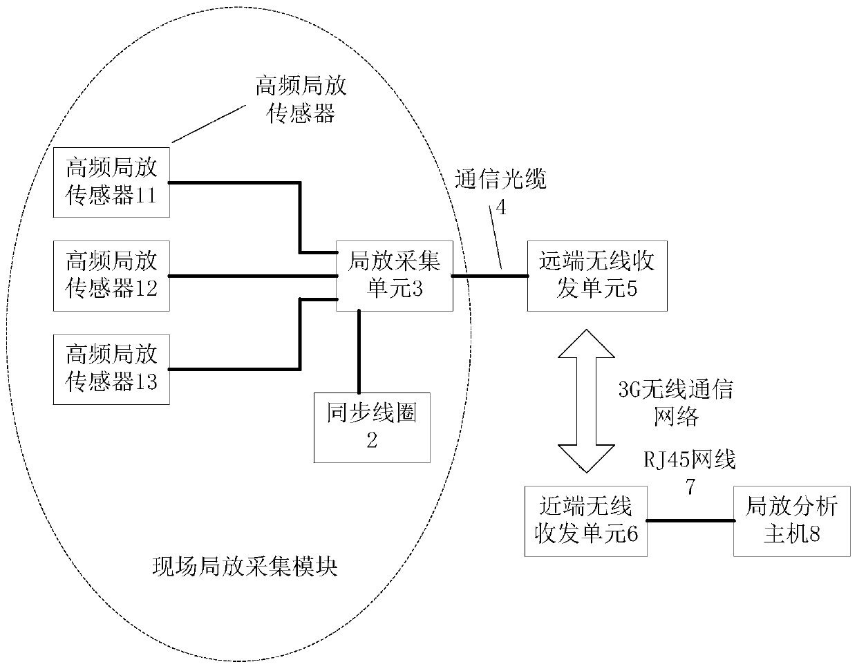
[0041] Such as figure 1 As shown, a mobile partial discharge remote diagnosis and detection system includes a high-frequency partial discharge sensor 1, a synchronous coil 2, a partial discharge acquisition unit 3, a communication optical cable 4, a remote wireless transceiver unit 5, a near-end wireless transceiver unit 6, RJ45 network cable 7, data analysis host 8. One end of the high-frequency partial discharge sensor 1 is connected to the cable terminal or the ground wire of the intermediate joint to obtain the partial discharge signal, and the other end is connected to the partial discharge acquisition unit 3, and the collected partial discharge information is transmitted to the partial discharge acquisition unit 3; the synchronous coil 2. One end is connected to the cable body, and the other end is connected to the partial discharge acquisition unit 3, and the a...


PUM


Abstract

The invention discloses a mobile partial discharge remote diagnosis and detection system and a partial discharge positioning method. The mobile partial discharge remote diagnosis and detection systemcomprises an on-site partial discharge acquisition module, a far-end wireless transceiving unit, a near-end wireless transceiving unit and a data analysis host. The on-site partial discharge acquisition module is connected with the far-end wireless transceiving unit through a communication optical cable. The on-site partial discharge acquisition module comprises a high-frequency partial dischargesensor, a synchronous coil and a partial discharge acquisition unit; the far-end wireless on-site element transmits partial discharge acquisition data to the near-end wireless on-site unit through a wireless network. And the near-end wireless transceiving unit is connected with the partial discharge analysis host through an RJ45 network cable. The detection system can change an installation placeaccording to requirements, perform fixed-point continuous monitoring on the partial discharge state quantity within a certain period of time under an operation condition, and upload monitoring data toa remote diagnosis host for storage, management and comprehensive analysis. The main step of the detection method is to locate the partial discharge.

Description

technical field [0001] The invention relates to the technical field of high-voltage power cable insulation detection, in particular to a mobile partial discharge remote diagnosis and detection system and a partial discharge positioning method. Background technique [0002] The early performance degradation or service life of XLPE power cables largely depends on the dendritic aging of the XLPE insulation medium. Partial discharge measurement is one of the effective methods for quantitative analysis. Its working principle is that partial discharge excites electromagnetic wave signals. The signals are sensed by built-in or external sensors. The signals pass through coaxial cables and are collected by the acquisition unit, so that the cables can be detected in time. And the insulation defect of the joint, and provide a criterion for evaluating its insulation level and aging degree, and provide a basis for the maintenance work of the cable. At present, there are usually two meth...

Claims


Application Information

Patent Timeline
IPC IPC(8): G01R31/12G08C17/02
CPCG01R31/1272G08C17/02
Inventor 沈跃蒋冬生
Owner JIANGSU UNIV
Why Eureka
Try Eureka