
Medical anti-falling handrail

An anti-fall and armrest technology, applied in the medical field, can solve problems such as unfavorable getting up, standing firm, prone to falling, space limitation, etc., achieving the effects of not easy to let go, improved safety, and convenient use.

Active Publication Date: 2020-08-18
ZIGONG NO 4 PEOPLES HOSPITAL
View PDF11 Cites 2 Cited by
  • Summary
  • Abstract
  • Description
  • Claims
  • Application Information

AI Technical Summary

Problems solved by technology

[0002] Whether it is side walls or vertical handrails are often limited by space, especially in hospitals, the use is very limited, vertical handrails put patients at risk of tripping
At the same time, such handrails are not conducive to the completion of actions such as getting up and standing firmly after the patient goes to the toilet.
Patients with unstable standing and poor muscle strength are still prone to falls. At this stage, there is no handrail that can provide dynamic and full-range assistance during the process of toileting to ensure the safety of patients.

Method used


Image

  • Medical anti-falling handrail
  • Medical anti-falling handrail
  • Medical anti-falling handrail

Examples


Embodiment 1

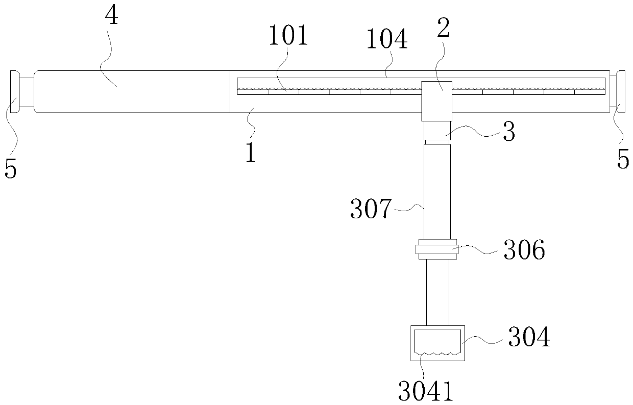
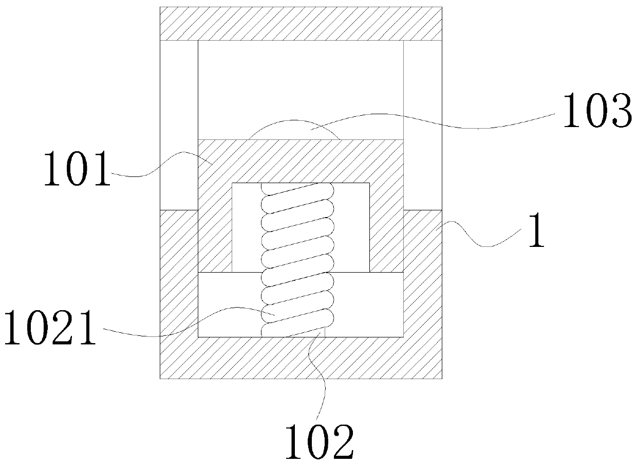
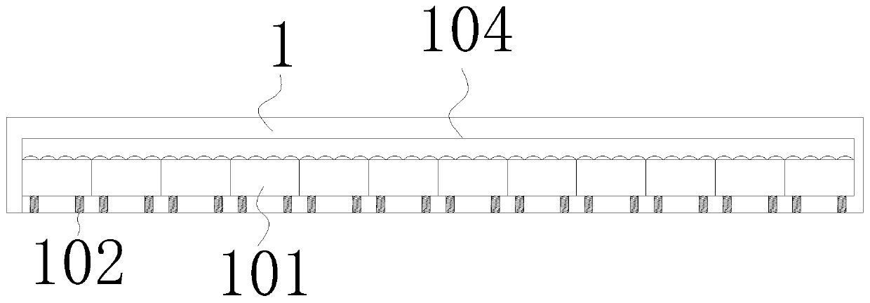
[0030] Such as Figure 1 to Figure 5 As shown, a medical anti-fall handrail includes a rectangular hollow connecting frame 1, and a plurality of rectangular top blocks 101 are arranged side by side in the connecting frame 1 and are mutually contradictory and connected to the bottom surface by two first telescopic rods 102 at the bottom. A telescoping rod 102 is sleeved with a compression spring 1021. By setting the compression spring 1021, the top block 101 can be restored to its original position after being squeezed to the bottom surface in the connection frame 1. The connection frame 1 is arranged along the long side of the top block 101 in the direction of extension. Bar-shaped through-holes 104 are provided on the opposite side wall surfaces, and the bottom surface of the top block 101 is lower than the edge of the bottom of the through-hole 104. There is a "mouth"-shaped rectangular briquetting block 2 that runs through the through holes 104 on both sides of the connecti...

Embodiment 2

[0032] Compared with embodiment 1, it also includes the following technical solutions: as figure 1 with Image 6 As shown, the support mechanism includes a fixed block 3 connected with the bottom of the pressing block 2 and provided with a plain thread, a second telescopic rod 307 movably connected with the fixed block 3 and a handle 304 arranged at the bottom of the second telescopic rod 307. The telescopic rod 307 includes an outer rod 302 and an inner rod 303 which are nested in each other. A telescopic spring 305 is connected between the outer rod 302 and the inner rod 303. The rebound of the second telescopic rod 307 can be realized by setting the yellow spring of the telescopic rod. When standing, the second telescopic rod 307 is contracted. When the patient gradually squats down, the second telescopic rod 307 gradually stretches to the height of the patient's squatting with the potential energy of gravity, so that the patient can support and stabilize it when going to t...

Embodiment 3

[0034] Compared with embodiment 2, it also includes the following technical solutions: as figure 1 with Image 6 As shown, the seat tube clip 306 is sleeved on the second telescopic rod 307, and the telescopic length of the second telescopic rod 307 can be adjusted and fixed through the seat tube clip 306. Some patients with weak or missing muscles cannot hold the second telescopic rod for a long time. The second telescopic rod 307 is stretched and held, which may easily cause the grip to fall off. By directly adjusting the length of the second telescopic rod 307 with the height of the patient when going to the toilet and clamping and fixing it, it is more convenient for such patients to use. After going to the toilet, only need to open the seat tube clip 306 and the second telescopic rod 307 will be retracted, and the patient can hold it and move towards the toilet door.


PUM


Abstract

The invention discloses a medical anti-falling handrail. The medical anti-falling handrail comprises a hollow connecting frame, a plurality of top blocks are arranged in the connecting frame side by side; a first telescopic rod is sleeved with a pressure spring; and through holes are formed in the two opposite side wall faces, in the arrangement and extension direction of the ejector blocks, of the connecting frame. The bottom surfaces of the top blocks are lower than the edges of the bottoms of the through holes; a square pressing block penetrating through the two through holes is arranged inthe connecting frame; the top wall surfaces in the pressing blocks are propped against the top surfaces of the top blocks; the bottoms of the pressing blocks are connected with a supporting mechanismfor supporting a patient; fixing mechanisms connected with a wall body are arranged at the two ends, facing the opening of the pressing blocks, of the connecting frame. When a patient is located at atoilet and squats, the pressing blocks exert downward force on one of the ejecting blocks in the connecting frame to enable the ejecting block to contract, meanwhile, the ejecting blocks located on the two sides of the contracting ejecting block conduct movement limiting on the pressing block moving downwards, the pressing block is clamped between the two ejecting blocks to be fixed, and it is guaranteed that the supporting device is fixed and cannot be dislocated when a patient goes to the toilet.

Description

technical field [0001] The invention relates to the medical field, in particular to a medical anti-fall handrail. Background technique [0002] Whether it is side walls or vertical handrails are often limited by space, especially in hospitals, the use is very limited, vertical handrails put patients at risk of tripping. Simultaneously, this type of handrail is not conducive to the completion of actions such as getting up and standing firmly after the patient goes to the toilet. Patients with unstable standing and poor muscle strength are still prone to falls. At this stage, there is no handrail that can provide dynamic and full-range assistance during the process of going to the toilet to ensure the safety of patients. Contents of the invention [0003] In view of the above problems, the present invention provides a medical anti-fall handrail, which has the advantage of helping patients with insufficient muscle strength to provide portable support when going to the toilet...

Claims


Application Information

Patent Timeline
Patent Type & Authority Applications(China)
IPC IPC(8): A47K17/02
CPCA47K17/022
Inventor 袁文洁张红梅徐冬兰陈雪莲但佳
Owner ZIGONG NO 4 PEOPLES HOSPITAL
Learn More