Two-section type parallel projection support device for shooting root tip piece

A stent device, a two-stage technology, applied in the field of medical devices, can solve the problems of stent deformation and aging, cost exceeding charging pricing, affecting imaging quality, etc., achieving the effects of small deformation, convenient shooting and observation, and compact and flexible structure

Inactive Publication Date: 2020-08-18
SICHUAN UNIV
View PDF0 Cites 0 Cited by
  • Summary
  • Abstract
  • Description
  • Claims
  • Application Information

AI Technical Summary

Problems solved by technology

[0005] However, there are technical problems in the parallel projection technology itself. At present, the price of a set of parallel projection brackets on the market is several times more expensive than the price charged for apical radiographs, and the cost of disinfecting a set of brackets often exceeds the price charged.
Therefore, the development and use of parallel projection technology in practical applications are limited.
In addition, the tube rings of most parallel projection brackets are mostly in contact with the tube but not fixed, so it is easy to move when placing the tube position, which affects the image quality
Repeated disinfection of the parallel projection bracket is also likely to cause deformation and aging of the bracket, affecting the use

Method used


Image

  • Two-section type parallel projection support device for shooting root tip piece
  • Two-section type parallel projection support device for shooting root tip piece
  • Two-section type parallel projection support device for shooting root tip piece

Examples


Embodiment 1

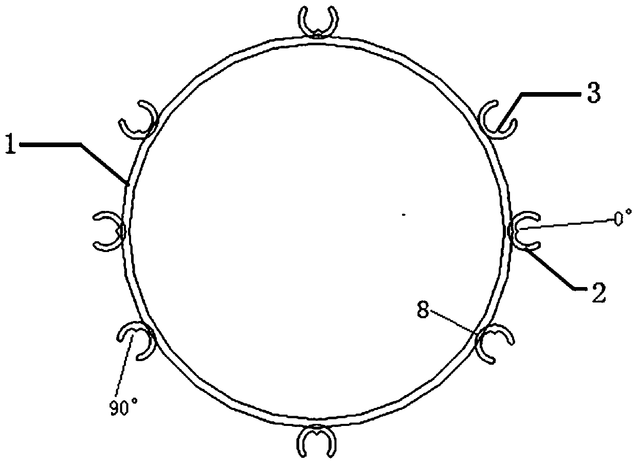
[0062] A two-stage parallel projection stent device for shooting apical slices, including a tube fixing ring and a disposable film holding clip, the fixing ring is provided with a ring body and N U-shaped grooves, N=8; U-shaped grooves Set on the outer surface of the ring; the disposable holding clip includes an extension part, a connecting rod, an engaging part and a holding part. The holding part is connected to one end of the engaging part, and both ends of the connecting rod are respectively connected to the extending part and the other end of the engaging part Vertical connection, the extension part is parallel to the occlusal part and the extension direction is opposite; one end of the connecting rod is perpendicularly connected to the extension part, and the other end of the extension part extends into the U-shaped groove, so that the fixing ring and the disposable holding clip are fixedly connected into one body.

[0063] The tube fixing ring is an X-ray tube fixing ring. ...

Embodiment 2

[0075] A two-stage parallel projection stent device for photographing apical slices, including a tube fixing ring and a disposable film holding clip, the fixing ring is provided with a ring body and N U-shaped grooves, N=8; U-shaped grooves Set on the outer surface of the ring; the disposable holding clip includes an extension part, a connecting rod, an engaging part and a holding part. The holding part is connected to one end of the engaging part, and both ends of the connecting rod are respectively connected to the extending part and the other end of the engaging part Vertical connection, the extension part is parallel to the occlusal part and the extension direction is opposite; one end of the connecting rod is perpendicularly connected to the extension part, and the other end of the extension part extends into the U-shaped groove, so that the fixing ring and the disposable holding clip are fixedly connected into one body.

[0076] The tube fixing ring is an X-ray tube fixing r...

Embodiment 3

[0097] Other contents are as in Example 1. The inner diameter of the ring is 68mm, the thickness of the ring is ≥3mm, and the width of the ring is 10mm.

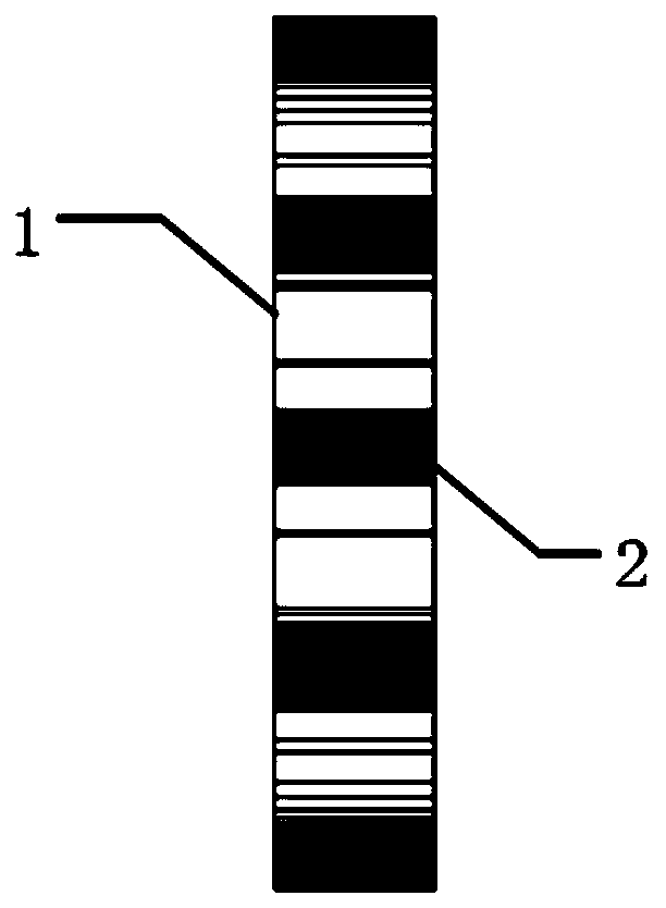
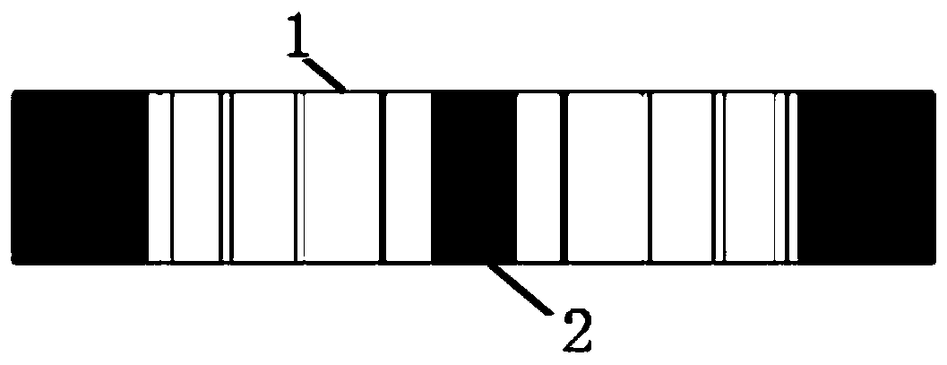
[0098] The length of the U-shaped groove is 20mm, the inner diameter of the groove is 10mm, and the concave point of the groove is the starting point and the measuring height is 5.8mm. The built-in slide rail has a width of 10 or 20mm, a length of 1 or 3mm, and a height of 0.5 or 1.5mm. The size matches the shape and size of the built-in positioning convex on the U-shaped groove. The extension is a rod-shaped long cylinder with a size of 50 or 100 mm in length and a cross-sectional diameter of 3 or 10 mm.

[0099] The occlusal part of the anterior teeth is a long square with dimensions of 10 or 20 mm in length, 20 or 40 mm in width and 7 or 15 mm in height.

[0100] When shooting the apical film, the parallel projection technology is used, and the parallel projection bracket conforming to the principle of parallel projection techn...


PUM

PropertyMeasurementUnit
Diameteraaaaaaaaaa
Thicknessaaaaaaaaaa
Ring widthaaaaaaaaaa

Abstract

The invention belongs to the field of medical apparatus and instruments, and particularly relates to a two-section type parallel projection support device for shooting a root tip film by adopting a parallel projection technology, which is characterized by comprising a bulb tube fixing ring and a disposable sheet holding clamp, the fixing ring is provided with a ring body and N U-shaped grooves, Nis greater than or equal to 1, the U-shaped grooves are formed in the outer surface of the ring body, the disposable sheet holding clamp comprises an extending part, a connecting rod, an occlusion part and a sheet holding part, the sheet holding part is connected with one end of the occlusion part, the two ends of the connecting rod are perpendicularly connected with the extending part and the other end of the occlusion part respectively, the extending part is parallel to the occlusion part and opposite to the occlusion part in extending direction, one end of the connecting rod is vertically connected with the extending part, and the other end of the extending part extends into the U-shaped groove, so that the fixing ring and the disposable sheet holding clamp are fixedly connected into awhole. According to the device, the relative positions and angles of the bulb tube and illuminated teeth are fixed through the parallel projection technology, only the disposable sheet holding clamp needs to be replaced during shooting, on one hand, the disinfection or consumable cost is reduced, on the other hand, the shooting technology difficulty is reduced, and the accuracy is improved.

Description

Technical field [0001] The invention belongs to the field of medical equipment, and in particular relates to a two-stage parallel projection bracket device for photographing apical slices. Background technique [0002] Apical radiographs are the most commonly used imaging diagnostic technology in oral clinical work, and are widely used in daily diagnosis and treatment in dental pulp, periodontal, alveolar surgery, restoration implants, and even orthodontics. [0003] The shooting technology of apical film mainly includes two types: angle bisector technology and parallel projection technology. Among them, the angle bisector technology is widely used, and has the advantages of not requiring additional device assistance, only requiring the patient's fingers or a film holder to fix the film; the disadvantage is that the technical difficulty is high, the shooting quality is unstable, and the distortion rate is high. Although the parallel projection technology has low technical difficul...

Claims


Application Information

Patent Timeline
IPC IPC(8): A61B6/14A61B6/00
CPCA61B6/40A61B6/4405A61B6/4429A61B6/512A61B6/51
Inventor 游梦石宇超任家银刘媛媛王虎王凯利王扬
Owner SICHUAN UNIV
Why Eureka
Try Eureka