
A gear end surface grinding device for gear processing

A gear end and gear technology, applied in the field of gear processing, can solve the problems of low grinding efficiency of the gear end face, inconvenient waste disposal, etc., and achieve the effects of simple structure, improved grinding efficiency, and convenient use

Active Publication Date: 2021-10-15
金华新天齿轮有限公司
View PDF2 Cites 1 Cited by
  • Summary
  • Abstract
  • Description
  • Claims
  • Application Information

AI Technical Summary

Problems solved by technology

[0004] The purpose of the present invention is to solve the disadvantages of low gear end face grinding efficiency in the prior art, and it is inconvenient to process waste during grinding, and proposes a gear end face grinding device for gear processing

Method used


Image

  • A gear end surface grinding device for gear processing
  • A gear end surface grinding device for gear processing
  • A gear end surface grinding device for gear processing

Examples


Embodiment 1

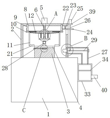
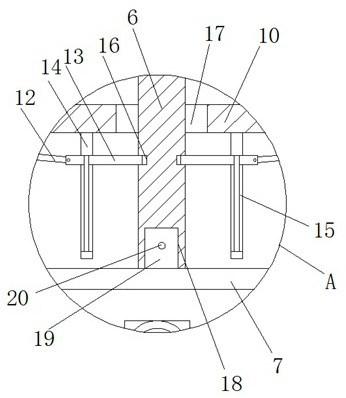
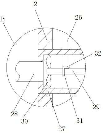
[0029] refer to Figure 1-5 , a gear end surface grinding device for gear processing, comprising a placing seat 1, a placing table 3 is fixedly installed on the top of the placing seat 1, the top of the placing table 3 is provided with a first grinding plate 4, and the top of the first grinding plate 4 is provided with There is a second polishing plate 7, the top of the second polishing plate 7 is provided with a push column 6, the top of the placement seat 1 is fixedly installed with a frame 2, the bottom of the frame 2 is rotatably installed with an annular plate 9, and the bottom of the annular plate 9 is fixedly installed with a The fixing plate 10, the fixing plate 10 is provided with a through hole 17, the bottom of the push column 6 passes through the through hole 17, the bottom of the fixing plate 10 is slidably installed with two push plates 11, and the two push plates 11 are rotated on the side close to each other One end of the push rod 12 is installed, the other en...

Embodiment 2

[0040] refer to Figure 1-5 , a gear end surface grinding device for gear processing, comprising a placing seat 1, the top of the placing seat 1 is fixedly installed with a placing table 3 by bolts, the top of the placing table 3 is provided with a first grinding plate 4, A second polishing plate 7 is arranged above, a push column 6 is arranged on the top of the second polishing plate 7, a frame 2 is fixedly installed on the top of the placing seat 1 by bolts, and an annular plate 9 is installed at the bottom of the frame 2. A fixing plate 10 is fixedly installed at the bottom by bolts, the fixing plate 10 is provided with a through hole 17, the bottom of the push column 6 penetrates the through hole 17, and the bottom of the fixing plate 10 is slidably installed with two push plates 11, and the two push plates 11 are mutually One end of the push rod 12 is rotatably installed on the adjacent side, and the other end of the two push rods 12 is rotatably installed with a lift rod...


PUM


Abstract

The invention belongs to the field of gear processing, in particular to a gear end face grinding device for gear processing. Aiming at the problems that the existing gear end face grinding efficiency is low and it is inconvenient to process waste during grinding, the following proposal is now proposed, It includes a placement seat, a placement table is fixedly installed on the top of the placement seat, a first grinding plate is provided on the top of the placement table, a second grinding plate is provided above the first grinding plate, and a pushing plate is provided on the top of the second grinding plate. A column, the top of the placement seat is fixedly installed with a frame, the bottom of the frame is rotatably installed with an annular plate, the bottom of the annular plate is fixedly installed with a fixed plate, and a through hole is opened on the fixed plate, and the bottom of the push column penetrates through the hole. Two push plates are slidingly installed on the bottom of the fixed plate. The invention can simultaneously grind the two end faces of the gear, improve the grinding efficiency, and can collect and process the grinding waste and dust. The structure is simple and easy to use.

Description

technical field [0001] The invention relates to the technical field of gear processing, in particular to a gear end surface grinding device for gear processing. Background technique [0002] Gear refers to a mechanical element on the rim that continuously meshes with gears to transmit motion and power. The end face of the gear needs to be ground flat during processing. [0003] In the prior art, the grinding efficiency of the gear end face is low, and it is inconvenient to handle the waste during grinding. Therefore, we propose a gear end face grinding device for gear processing to solve the above problems. SUMMARY OF THE INVENTION [0004] The purpose of the present invention is to solve the disadvantages of low gear end surface grinding efficiency and inconvenient disposal of waste during grinding in the prior art, and proposes a gear end surface grinding device for gear processing. [0005] In order to achieve the above object, the present invention adopts the followin...

Claims


Application Information

Patent Timeline
Patent Type & Authority Patents(China)
IPC IPC(8): B24B7/17B24B27/00B24B55/06B24B55/12B24B41/06
CPCB24B7/17B24B27/0076B24B27/0092B24B41/06B24B55/06B24B55/12
Inventor 曹延昌
Owner 金华新天齿轮有限公司
Learn More