
Crane for installing and maintaining wind driven generator

A crane and boom technology, applied in the field of cranes for installation and maintenance of wind power generation, can solve the problems of high installation and maintenance costs, poor mobility, poor mobility, etc. effect of ability

Pending Publication Date: 2020-08-18
系泰能源科技(苏州)有限公司
View PDF0 Cites 1 Cited by
  • Summary
  • Abstract
  • Description
  • Claims
  • Application Information

AI Technical Summary

Problems solved by technology

The cost of large-scale cranes is high, the structure of the crane is large, the cycle of disassembly and transportation is long, and the mobility is poor, especially for the installation and maintenance of fans in distributed wind farms
Marine wind turbines generally use large hoisting ships to install and maintain wind turbines. The installation and maintenance costs are very high and the mobility is poor.

Method used


Image

  • Crane for installing and maintaining wind driven generator
  • Crane for installing and maintaining wind driven generator
  • Crane for installing and maintaining wind driven generator

Examples


Embodiment 1

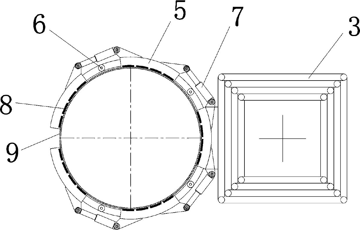
[0020] see Figure 1-Figure 5 , the present embodiment includes a boom 1, a slewing bearing 2, a crane lifting base 3 and multiple sets of electromagnet adsorption devices 4, the boom 1 is installed on the crane lifting base 3 through the slewing bearing 2, and the crane lifting base 3 is multiple Section bar structure, the present embodiment is a four-section bar.

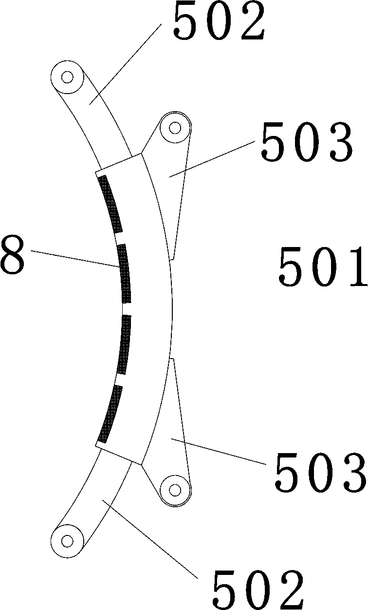
[0021] In this embodiment, the number of electromagnet adsorption devices 4 is the same as the number of rod sections of the lifting base 3 of the crane, which is four sets of electromagnet adsorption devices 4 . Each group of electromagnet adsorption devices 4 is fixedly installed on the side position of the top of each bar, and its fixed installation method can be welding, bolt connection or hinge, etc., and the present embodiment is welding and fixing. When necessary, if you run into a fan tower 9 with a special shape, you can also install an electromagnet adsorption device 4 on the side of other positions of ...

Embodiment 2

[0029] see Figure 10-Figure 11 , the present embodiment includes a boom 1, a slewing bearing 2, a crane lifting base 3 and multiple sets of electromagnet adsorption devices 4, the boom 1 is installed on the crane lifting base 3 through the slewing bearing 2, and the crane lifting base 3 is multiple Sectional plate structure, the present embodiment is four section plate.

[0030] The rest of the structure and working process of this embodiment are the same as those of Embodiment 1 and will not be repeated here.


PUM


Abstract

The invention discloses a crane for installing and maintaining a wind driven generator, and particularly relates to the crane for installing and maintaining the wind driven generator. The crane comprises a suspension arm, a pivotal bearing and a crane lifting base, the suspension arm is installed on the crane lifting base through the pivotal bearing, the crane lifting base is of a multi-section lifting structure, and the crane is structurally characterized by further comprising a plurality of sets of electromagnet attraction devices which are fixedly installed on the side face position of thecrane lifting base; and each set of electromagnet adsorption device comprises a plurality of electromagnet adsorption units, the electromagnet adsorption units are sequentially connected with a telescopic hydraulic cylinder through hinges, and the inner walls of the electromagnet adsorption units are in a circular arc shape and provided with electromagnets. The crane for installing and maintainingthe wind driven generator has the advantages of being simple in structure, high in maneuverability and capable of reducing the installation and maintenance cost of the wind driven generator.

Description

technical field [0001] The invention relates to a crane for installing and maintaining a wind power generator, in particular to a crane for installing and maintaining a wind power generator. Background technique [0002] Wind energy is a kind of clean and pollution-free renewable energy. The use of wind power to generate electricity is very environmentally friendly, and the wind energy reserves are huge, so it is increasingly valued by countries all over the world. Offshore wind power is an important field of renewable energy development, an important force to promote wind power technology progress and industrial upgrading, and an important measure to promote energy structure adjustment. [0003] At present, land wind turbines are generally installed with large cranes, such as truck cranes, crawler cranes, tower cranes, etc. The overall height of the crane needs to be higher than the height of the wind turbine to complete the installation and maintenance of the wind turbine....

Claims


Application Information

Patent Timeline
Patent Type & Authority Applications(China)
IPC IPC(8): B66C23/30B66C23/20B66C23/78
CPCB66C23/20B66C23/30B66C23/78
Inventor 范晓刚居新峰丰超陈扣化史文韬李春颖李笑梅范东明马超田新明
Owner 系泰能源科技(苏州)有限公司
Learn More