
Field testing equipment and method for heat transfer coefficient of building envelope

A building envelope structure and heat transfer coefficient technology, applied in the direction of material thermal conductivity, material thermal development, etc., can solve the problems of heat transfer coefficient deviation, difficult installation, long test time, etc., to achieve simple equipment structure and small calculation error , The effect of small programming difficulty

Active Publication Date: 2022-04-26
SOUTHEAST UNIV
View PDF6 Cites 0 Cited by
  • Summary
  • Abstract
  • Description
  • Claims
  • Application Information

AI Technical Summary

Problems solved by technology

However, these methods have more or less limitations. The hot box method is mainly used for laboratory testing and research. Because the equipment is not easy to install and the cost is high, it is not easy to use for field testing.
Although the heat flow meter method is the preferred method of the national standard, it is also an internationally recognized method, but the premise of the field test of this method must be the heating period, which is strongly affected by the season. The temperature control box-heat flow meter method combines the advantages of the two to a certain extent. Combination is a relatively excellent on-site detection method, but the heat transfer coefficients tested by different equipment produced by different companies have deviations, and there is a gap of 10% to 25% in the results, and the test time is long, and it takes a long time to obtain The heat transfer coefficient of the tested enclosure structure

Method used


Image

  • Field testing equipment and method for heat transfer coefficient of building envelope

Examples


Embodiment Construction

[0022] The technical solutions of the present invention will be further described below in conjunction with the accompanying drawings and embodiments.

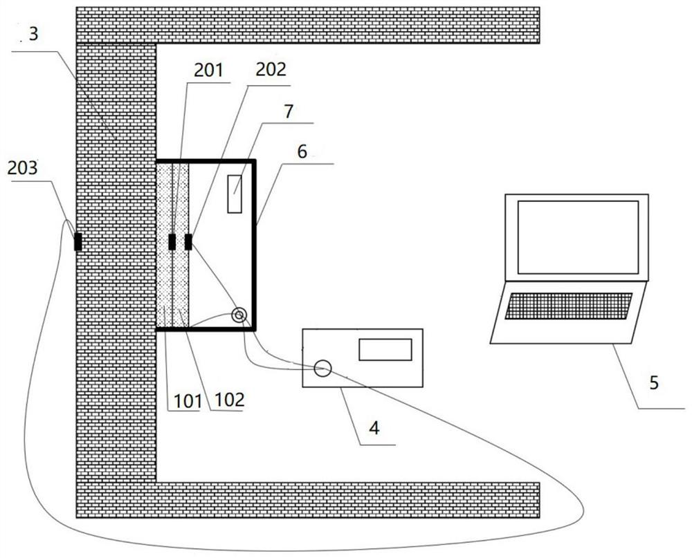
[0023] Such as figure 1 The on-site test equipment for the heat transfer coefficient of the building envelope shown, including the main part of the equipment and the data acquisition and processing part;

[0024] The main part of the device includes: a first auxiliary test material plate 101, a second auxiliary test material plate 102, a first temperature sensor 201, a second temperature sensor 202 and a third temperature sensor 203, the first auxiliary test material plate 101 Close to the inner surface of the enclosure structure 3 to be tested, the second auxiliary test material plate 102 is close to the outer surface of the first auxiliary test material plate 101, and the first temperature sensor 201 is arranged on the first auxiliary test material plate 101. The joint between the plate 101 and the second auxiliary test mat...


PUM

PropertyMeasurementUnit
thermal conductivityaaaaaaaaaa
thicknessaaaaaaaaaa
densityaaaaaaaaaa

Abstract

The invention discloses an on-site testing device for the heat transfer coefficient of a building enclosure structure, which includes a main part of the device and a data acquisition and processing part; the main part of the device includes: a first auxiliary test material board, a second auxiliary test material board, and a first temperature sensor , a second temperature sensor and a third temperature sensor; the data acquisition and processing part includes: data acquisition equipment and a computer, based on the one-dimensional heat conduction differential equation inside the multi-layer material, the analytical solution to the heat transfer coefficient is realized. Also disclosed is a field testing method for the heat transfer coefficient of the building enclosure structure. The equipment is simple in structure, easy to carry and easy to install. The test site can be flexibly selected according to the needs. The comprehensive heat transfer coefficient of the test enclosure structure can be measured more accurately in a short period of time, and the test site can be flexibly heated. The test results are not affected by the external temperature; secondly, the calculation program of this test method is based on the basic heat conduction equation, which has small programming difficulty and small calculation error.

Description

technical field [0001] The invention relates to the field of building performance testing, in particular to an on-site testing device and method for heat transfer coefficient of building envelope structures. Background technique [0002] As a major source of power for the continuous development of human society, energy has always been a topic of constant discussion and research. In today's environment where all walks of life in the world continue to move forward, energy has gradually begun to take off in the process of global steady development. There is a constraint, and the impact of this constraint is growing. As we all know, building energy consumption occupies a considerable share in the total energy consumption of the society from beginning to end, and building energy conservation is the key to solving the global energy shortage in the future and realizing CO2 in various countries. 2 Therefore, the topic of building energy efficiency is becoming more and more serious ...

Claims


Application Information

Patent Timeline
Patent Type & Authority Patents(China)
IPC IPC(8): G01N25/20G01N25/18
CPCG01N25/20G01N25/18
Inventor 金星张赟石邢江玥
Owner SOUTHEAST UNIV
Learn More