Pulse delay time control method and device

A technology of pulse delay and delay time, which is applied in the field of measurement, can solve the problems of increasing hardware overhead and testing cost, and achieve the effect of saving testing and hardware overhead costs

Active Publication Date: 2020-08-18
炬佑智能科技(苏州)有限公司
View PDF6 Cites 3 Cited by
  • Summary
  • Abstract
  • Description
  • Claims
  • Application Information

AI Technical Summary

Problems solved by technology

And before each chip leaves the factory, a large number of measurement and calibration experiments need to be done to correct the error caused by the delay, which increases the hardware overhead and test cost

Method used


Image

  • Pulse delay time control method and device
  • Pulse delay time control method and device
  • Pulse delay time control method and device

Examples


Embodiment Construction

[0022] The above solution will be further described below in conjunction with specific embodiments. It should be understood that these examples are used to illustrate the present invention and not to limit the scope of the present invention. The implementation conditions adopted in the examples can be further adjusted as the conditions of specific manufacturers, and the implementation conditions not indicated are usually the conditions in routine experiments.

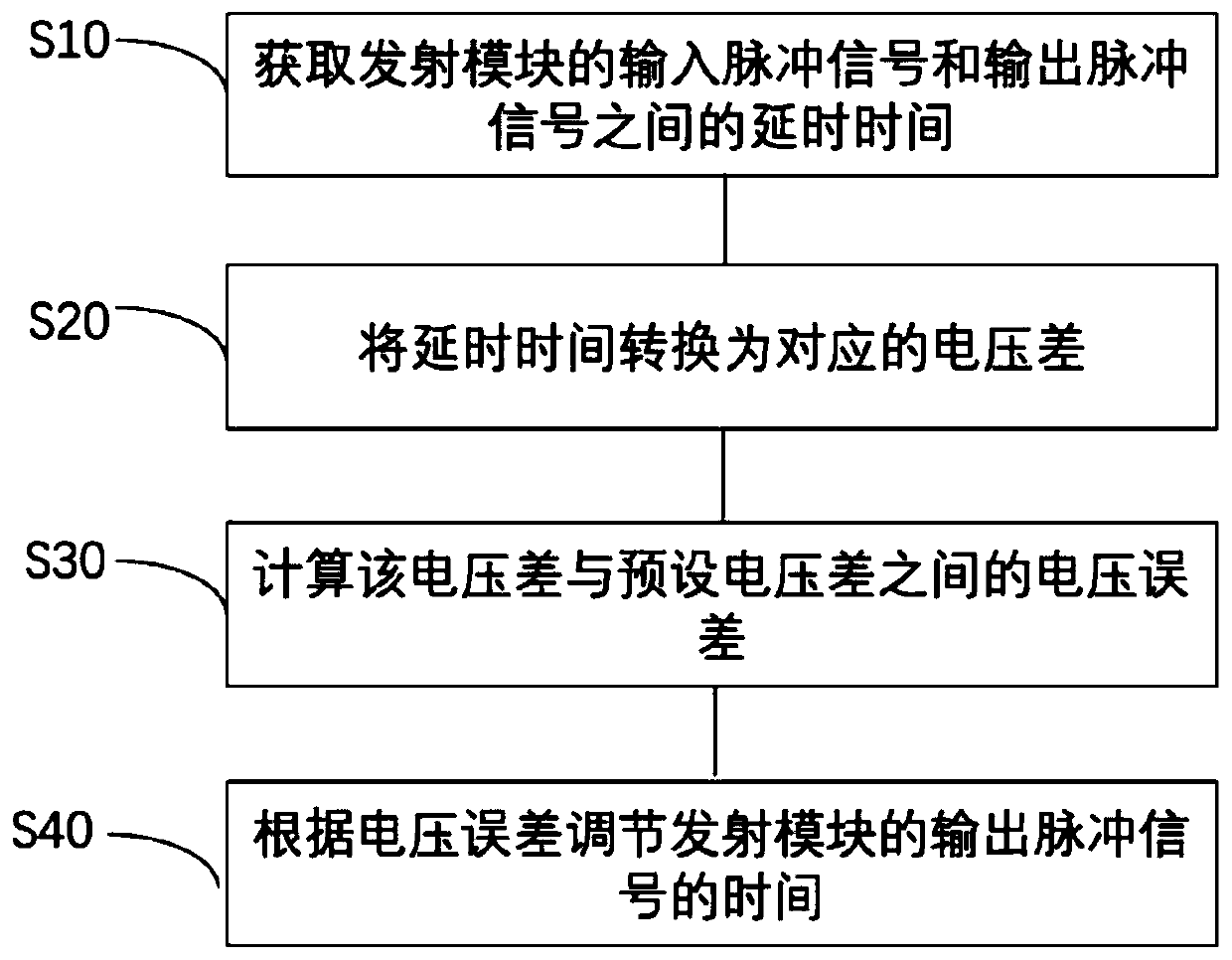
[0023] Please refer to figure 1 As shown, the present invention provides a kind of pulse delay time control method, and described method comprises the following steps:

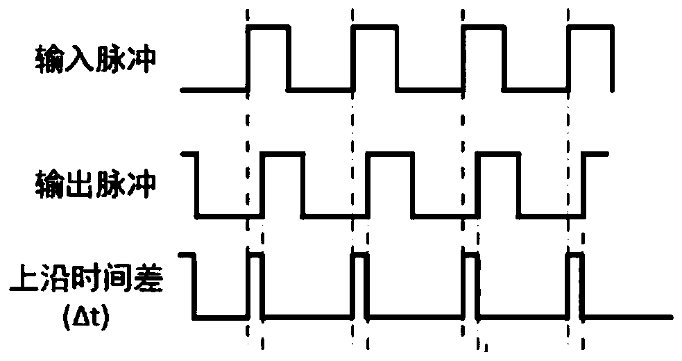
[0024] Step S10, acquiring the delay time between the input pulse signal and the output pulse signal of the transmitting module.

[0025] In one embodiment of the present invention, step S10 specifically includes the following steps:

[0026] Obtain the time difference between the rising edge of the input pulse signal of the transmitting module and t...


PUM


Abstract

The invention provides a pulse delay time control method and device. The control method comprises the following steps: acquiring delay time between an input pulse signal and an output pulse signal ofa transmitting module; converting the delay time into a corresponding voltage difference; calculating a voltage error between the voltage difference and a preset voltage difference; the time for outputting the pulse signal of the transmitting module is adjusted according to the voltage error, so that the output pulse is accurately controlled, the time difference of the edges of the input pulse andthe output pulse is not interfered by external factors such as voltage and temperature, and a large amount of test and hardware expenditure costs are saved.

Description

technical field [0001] The invention relates to the field of measurement technology, in particular to a pulse delay time control method and device. Background technique [0002] Most of the existing high-precision ranging solutions are by actively hitting the pulsed light waveform on the obstacle and receiving the reflected beam, and by comparing information such as time difference or phase difference between the emitted light and the reflected light, the distance is obtained by conversion. information. In recent years, there has been an increasing demand for high-precision ranging in short and medium distances. Therefore, the output power required by the light emitter is getting higher and higher, and the application environment is becoming more and more harsh. The anti-interference ability of the light emitter becomes a very important issue. Between the initial input pulse signal of the light emitter and the actual output pulse signal, due to the existence of the data l...

Claims


Application Information

Patent Timeline
Patent Type & Authority Applications(China)
IPC IPC(8): G01S17/10G01S7/484G01S7/4865
CPCG01S17/10G01S7/484G01S7/4865
Inventor 潘扬李丹
Owner 炬佑智能科技(苏州)有限公司
Why Eureka
Try Eureka