Corner plate of steel bar truss floor support plate and cast-in-place concrete beam

A technology of reinforced trusses and concrete beams, applied in the field of prefabricated buildings, can solve problems such as slurry leakage easily

Inactive Publication Date: 2020-08-21
SHANGHAI BAOYE GRP CORP
View PDF6 Cites 0 Cited by
  • Summary
  • Abstract
  • Description
  • Claims
  • Application Information

AI Technical Summary

Problems solved by technology

[0004] The purpose of the present invention is to provide a corner slab of a reinforced truss floor slab and a cast-in-place concrete beam, which effectively solves the problem of the rela

Method used


Image

  • Corner plate of steel bar truss floor support plate and cast-in-place concrete beam
  • Corner plate of steel bar truss floor support plate and cast-in-place concrete beam
  • Corner plate of steel bar truss floor support plate and cast-in-place concrete beam

Examples


Embodiment Construction

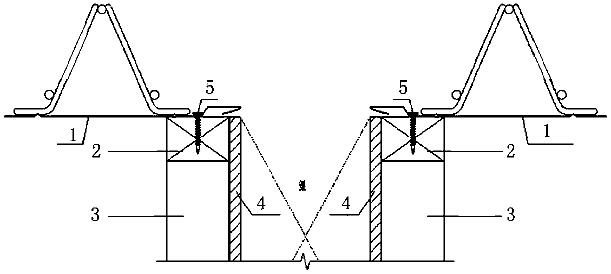
[0025] The core of the present invention is to provide a corner slab of reinforced truss floor slab and cast-in-place concrete beam, which effectively solves the problem of the relationship between reinforced truss slab and cast-in-place concrete beam during concrete pouring. Concrete beam joints are prone to grout leakage.

[0026] The following will clearly and completely describe the technical solutions in the embodiments of the present invention with reference to the accompanying drawings in the embodiments of the present invention. Obviously, the described embodiments are only some, not all, embodiments of the present invention. Based on the embodiments of the present invention, all other embodiments obtained by persons of ordinary skill in the art without making creative efforts belong to the protection scope of the present invention.

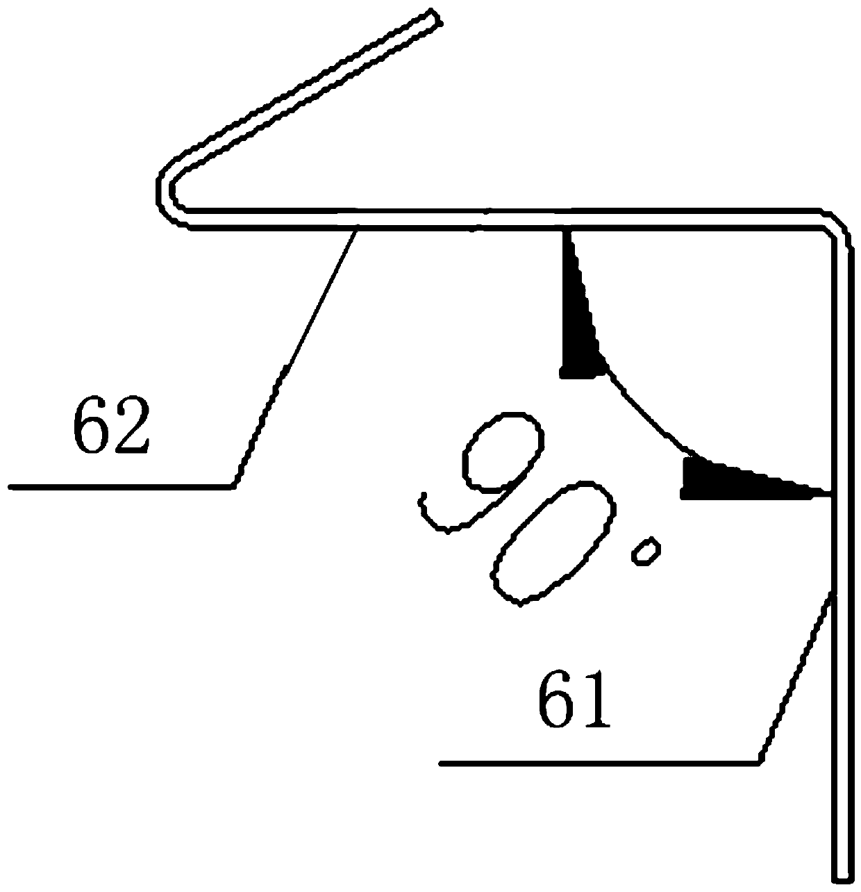
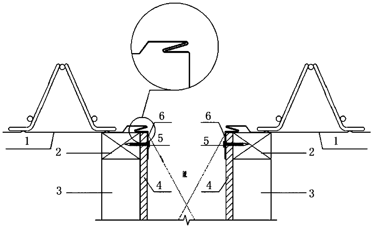
[0027] Please refer to figure 2 with image 3 , figure 2 Respectively, a schematic diagram of a reinforced truss floor deck and a c...


PUM

PropertyMeasurementUnit
Plate thicknessaaaaaaaaaa
Yield strengthaaaaaaaaaa
Lengthaaaaaaaaaa

Abstract

The invention discloses a corner plate of a steel bar truss floor support plate and a cast-in-place concrete beam. The corner plate comprises a corner plate body (61) which is composed of a vertical plate and a transverse plate, and a hook portion (62) which is connected with one end of the corner plate body (61); the hook portion (62) can be buckled with a male-female buckle of the steel bar truss floor support plate (1); an included angle between the vertical plate and the transverse plate of the corner plate body (61) is equal to an included angle between the upper end surface and the sidewall of a beam side mold (4); and the vertical plate of the corner plate body (61) is fixed to the side wall of the beam side mold (4). By means of the corner plate of the steel bar truss floor support plate and the cast-in-place concrete beam, the problem that mortar leakage is prone to occurring at a joint between the steel bar truss floor support plate and the cast-in-place concrete beam duringconcrete pouring is effectively solved.

Description

technical field [0001] The invention relates to the technical field of prefabricated buildings, in particular to a corner plate of a reinforced truss floor deck and a cast-in-place concrete beam. Background technique [0002] At the connection node between the traditional reinforced truss floor deck and the cast-in-place concrete beam, there is a certain gap between the bottom formwork of the reinforced truss floor deck and the connection node of the beam side formwork, resulting in grout leakage during concrete pouring, which affects the construction The material quality and appearance; and after the pouring is completed, the iron nails fixing the steel truss floor deck cannot be removed or need to be cut, which brings great inconvenience to the construction. Please refer to figure 1 , figure 1 It is a schematic diagram of connection nodes between a traditional reinforced truss floor deck and cast-in-place concrete beams in the prior art. [0003] To sum up, how to effec...

Claims


Application Information

Patent Timeline
IPC IPC(8): E04G13/00
CPCE04G13/00
Inventor 黄永胜李贤杰刘威张贵文王铮武涛
Owner SHANGHAI BAOYE GRP CORP
Why Eureka
Try Eureka